Representation of Geometric Objects
Geometric constraint solver works with a certain geometric object representation form shown in Fig. 1. All objects are expressed using point, vector and number coordinates (scalars).
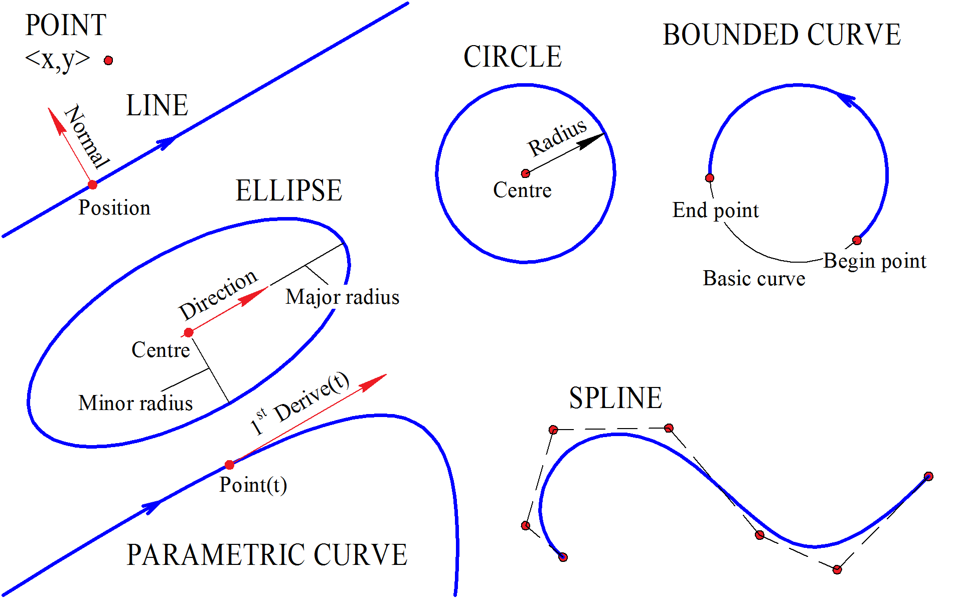
Fig. 1
The application can have its own representation of geometric objects that differs from solver representation. However, passing object status data in the solver and passing the calculation results back are based on the fact that each geometry type has its representation:
A point is represented by a pair of Cartesian coordinates <X,Y>.
A line is defined by its position point and a normal vector. It is assumed that a curve has a direction vector equal to the normal vector rotated 90 degrees clockwise. In other words, the normal with <Y,-X> coordinates will correspond to the direction vector with <X,Y> coordinates.
A circle is defined by its center point and a radius. C3D Solver supports circles with zero or positive radius. It is possible to specify to the C3D Solver that zero radius circles should be allowed on an individual basis using the GCE_allow_zero_radius callback function. Circles cannot have a negative radius. Note. The need for the zero radius option arises when solving the following problems:
constructing a parametric contour with disappearing and reappearing circular arcs;
construction of parametric 3D models with variable topology based on 2D contours;
construction of a surface along a trajectory of variable cross-section.
One example of applying the zero-radius option is modeling the surface of an air duct with a variable cross-section, specifically a rectangular section with rounded corners transitioning into a rectangle without rounded corners.
An ellipse is defined by its central point, radii along the major and minor semi-axes and the direction vector of the main semi-axis. Ellipse parameters are also defined by a periodic parameter ranging from 0 to 2\(\pi\) running the ellipse counterclockwise along its starting point at the main semi-axis.
A parametric curve is passed to the solver as MbCurve class. Such curve is considered to be fixed, and the calculations associated with this curve are based on the following virtual functions: MbCurve::PointOn, MbCurve::FirstDer and MbCurve::SecondDer, that return, correspondingly, the first point on the curve based on the parameter, the first or the second derivatives in the point. Parametric curves are described in more detail in Item General Parametric Curves.
Note. In the current version, you should create MbCurve instance in order to create a parametric curve in the constraint system. However, an alternate variant based on simple user-implemented functions will be implemented in future releases. C3D core user can also implement custom inheritors for the MbCurve class.
A spline uses NURBS representation based on a list of control points. Work with splines is described in more detail in Item General Parametric Curves.
A bounded curve is a curve portion bounded by end points on both sides. It is defined by three elements: a base curve, start and end points. C3D Solver supports a zero-length option for a bounded curve and line segment. In order to allow or prohibit the zero length of the curve on an individual basis, it is necessary to use the callback function GCE_allow_zero_length. By default, the zero-length option is disabled.