Directed Distance Dimension
A simple distance dimension measures a distance between points lying on geometric objects. A directed distance dimension is also defined for a pair of points, but the distance is measured between the projections of points along the line having a particular direction. This dimension type is mostly used to create vertical and horizontal dimensions that define the distance between points projected on X or Y axis. Fig. 1 shows the examples of vertical and horizontal dimensions for a point pair. Generally, the dimension direction can be arbitrary.
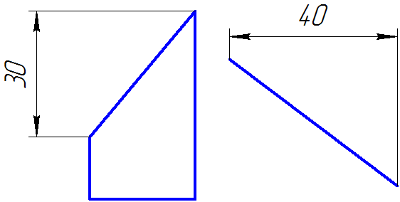 {width=”50%”}
Fig. 1
Directed dimensions also behave in a specific way during a geometric transformation of the sketch by the GCE_Transform() method. Directed dimension would rotate if the transformation matrix contains a rotation component.
Directed dimensions are created by the
{ll}
constraint_item GCE_AddDirectedDistance(GCE_system gSys, geom_item p[2]
                                     , const GCE_ldim_pars & dPars)
The function returns the descriptor of directed dimension.
The method input parameters are:
gSys is a parametric sketch constraint system;
p[2] are the descriptors of point pair;
dPars is a data structure, that besides standard settings inherent to distance dimensions (see similar settings for GCE_AddDistance()), additionally sets the dPars.dirAngle angular direction. For instance, if it is required to define a horizontal dimension, then dPars.dirAngle = \(0\); if it is required to define a vertical dimension, then dPars.dirAngle = \(\pi\)/2. Generally, dPars.dirAngle can range from \(0\) to \(2\pi\).
Note. In the current C3D Solver version, the directed dimension can be set only for points.