Constructing a Body by Sections
The function
MbResultType LoftedSolid( const MbLoftedSolidParams & loftSolParams,
                                c3d::SolidSPtr      & result );
constructs a body using spatial (including planar) sections.
The input parameter of the function is the loftSolParams object containing the initial data for the operation (definition of the MbLoftedSolidParams class, see op_shell_parameter.h).
The output parameter of the function is the constructed body result.
The function returns a result code of the operation from the MbResultType enumeration (see mb_operation_result.h).
The function is declared in the action_solid.h file.
The following constructors of the MbLoftedSolidParams class initialize the loftSolParams object with body construction parameters (see op_shell_parameter.h):
MbLoftedSolidParams( const std::vector<MbPlacement3D> &    places,
                     const c3d::PlaneContoursSPtrVector &  planeConours,
                     const c3d::ConstSpaceCurveSPtr &      spine,
                     const LoftedValues &                  params,
                     const c3d::SpaceCurvesSPtrVector *    guideCurves,
                     const c3d::SpacePointsVector *        guidePoints,
                     const MbSNameMaker &                  operName,
                     const c3d::SNamesMakerSPtrVector &    contourNames,
                           IProgressIndicator *            prog = nullptr );

MbLoftedSolidParams( const c3d::SurfacesSPtrVector &       surfaces,
                     const c3d::PlaneContoursSPtrVector &  planeConours,
                     const c3d::ConstSpaceCurveSPtr &      spine,
                     const LoftedValues &                  params,
                     const c3d::SpaceCurvesSPtrVector *    guideCurves,
                     const c3d::SpacePointsVector *        guidePoints,
                     const MbSNameMaker &                  operName,
                     const c3d::SNamesMakerSPtrVector &    contourNames,
                           IProgressIndicator *            prog = nullptr );

MbLoftedSolidParams( const std::vector<MbPlacement3D> &    places,
                     const c3d::PlaneContoursSPtrVector &  planeConours,
                     const c3d::ConstSpaceCurveSPtr &      spine,
                     const LoftedValues &                  params,
                     const OperationType                   oType,
                     const c3d::SpaceCurvesSPtrVector *    guideCurves,
                     const c3d::SpacePointsVector *        guidePoints,
                     const MbSNameMaker &                  operName,
                     const c3d::SNamesMakerSPtrVector &    contourNames,
                           IProgressIndicator *            prog = nullptr );

MbLoftedSolidParams( const c3d::SurfacesSPtrVector &       surfaces,
                     const c3d::PlaneContoursSPtrVector &  planeConours,
                     const c3d::ConstSpaceCurveSPtr &      spine,
                     const LoftedValues &                  params,
                     const OperationType                   oType,
                     const c3d::SpaceCurvesSPtrVector *    guideCurves,
                     const c3d::SpacePointsVector *        guidePoints,
                     const MbSNameMaker &                  operName,
                     const c3d::SNamesMakerSPtrVector &    contourNames,
                           IProgressIndicator *            prog = nullptr );
where
places – a set of local coordinate systems for generatrix contours.
planeConours – a set of generatrix contours.
surfaces – a set of surfaces of generatrix contours.
oType – Boolean operation type.
spine – spine curve (may be nullptr).
params – operation parameters.
guideCurves – a set of guide curves defining trajectories for corresponding contour points.
guidePoints – a set of points on generatrix contours defining corresponding points (point chains).
operName – operation namer.
contourNames – generatrix contour namers.
prog – operation progress indicator.
Constructing a Body by Planar Sections
The surface of a body constructed by planar sections passes through all planar curves defining the body. The places set contains local coordinate systems whose XY planes contain the 2D contours planeConours.
The places and planeConours sets are index-aligned: planeConours[i] lies in the XY plane of the local coordinate system places[i]. The orientation of planeConours can be arbitrary. If all planeConours are closed, contour start positions are adjusted to prevent surface twisting by placing the starts as close to each other as possible. The guidePoints control points allow changing the correspondence of curve junction points between contours. If the guidePoints set is non-empty, it must be coordinated with the places and planeConours sets. Guide curves guideCurves can be used to control the body shape between sections. Any curve can serve as the body spine curve.
The params parameter contains information about the movement method, presence and wall thickness of the body, and whether the constructed body is closed.
The params.thickness1 and params.thickness2 parameters define the wall thickness of the constructed thin-walled body. The params.thickness1 parameter specifies the outward offset from the generatrix curve, and the params.thickness2 parameter specifies the inward offset from the generatrix curve.
The params.shellClosed parameter controls whether the constructed body is closed (true – closed body; false – non-closed body).
The params.checkSelfInt parameter indicates whether the construction result should be checked for self-intersection. By default, params.checkSelfInt = false, and the check is not performed.
The mergeFlags control flags manage merging of similar faces or edges (mergeFaces = true – merge similar faces; mergeEdges = true – merge similar edges).
The params.closed parameter controls the closedness of the section tube (presence of end caps). When params.closed = true, end caps are absent and the body has torus topology. By default, params.closed = false.
The params.vector1 and params.vector2 vectors define the body direction near the initial and final end caps. For example, they allow setting the body direction near end caps orthogonal to end cap planes. By default, params.vector1 and params.vector2 are zero.
The params.setNormal1 and params.setNormal2 parameters set normals at the initial and final end caps respectively if the initial section is a point (by default false).
The params.derFactor1 and params.derFactor2 parameters set derivative magnitude multipliers when setting normals at the initial and final end caps respectively.
The params.directSurf1 and params.directSurf2 vectors define the surface movement direction axis at the initial and final end caps respectively when setting normals.
Fig. 1 shows the input data used for construction and the parameter inheritance scheme for constructing a body by planar sections MbLoftedSolidParams & loftSolParams:
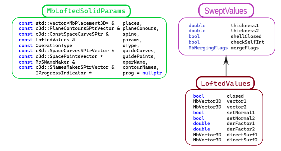
Fig. 1
The contourNames parameter provides naming for the faces of the constructed body.
Fig. 2 shows a set of 2D contours planeConours and their local coordinate systems places (arrows indicate the normal directions of the local coordinate systems):
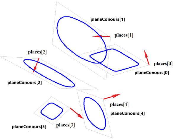
Fig. 2
Fig. 3 shows a closed body constructed by planar sections shown in Fig. 2, with specified normal directions at end caps for params.closed = false.
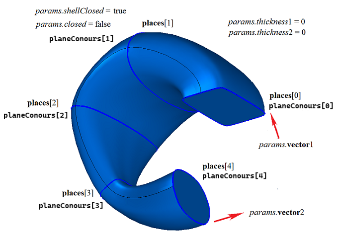
Fig. 3
Fig. 4 shows a closed body constructed by planar sections shown in Fig. 2, with params.closed = true. The constructed body has torus topology and lacks end caps.
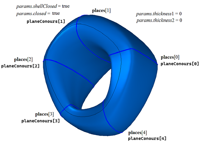
Fig. 4
Fig. 5 shows a closed thin-walled body constructed by planar sections shown in Fig. 2, without specified normals at end caps for params.closed = false:

Fig. 5
Fig. 6 shows a closed thin-walled body constructed by planar sections shown in Fig. 2, with specified normals at end caps for params.closed = false:
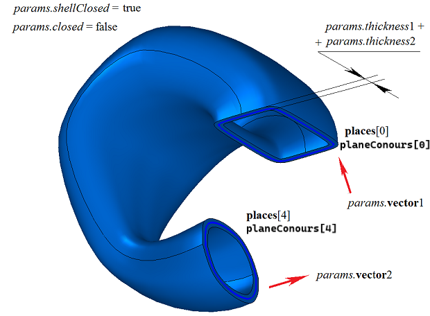
Fig. 6
Fig. 7 shows a closed thin-walled body constructed by planar non-closed contours without specified normals at end caps for params.closed = false. The params.thickness1 and params.thickness2 parameters must be non-zero.
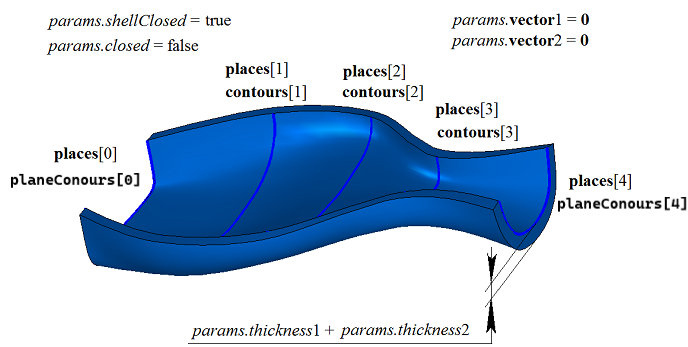
Fig. 7
Fig. 8 shows a non-closed body constructed by planar non-closed contours without specified normals at end caps for params.closed = false. The params.thickness1 and params.thickness2 parameters can be zero.
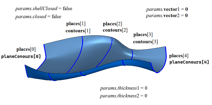
Fig. 8
When planar contours have different numbers of segments, some segments are subdivided so that each contour in the planeConours set has the same number of segments. Fig. 9 shows three contours with different numbers of segments.
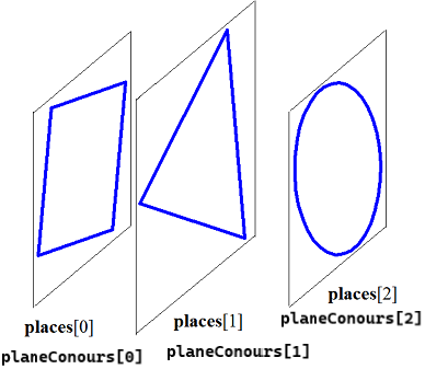
Fig. 9
Fig. 10 shows a closed body constructed from these contours, where one segment of the triangular contour is subdivided into two segments, and the circle is subdivided into four arcs:
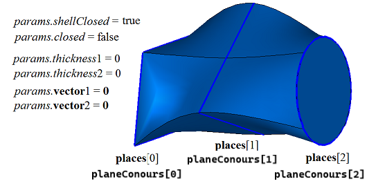
Fig. 10
The position of edges connecting vertices of different contours can be controlled using guidePoints control points. The guidePoints[i] points indicate segment junction positions between different contours that should be connected by edges. To demonstrate the use of guidePoints control points, consider constructing a body using planar sections shown in Fig. 11:
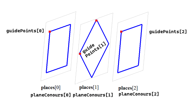
Fig. 11
Fig. 12 and 13 show bodies constructed using planar sections from Fig. 11 with different positions of guidePoints control points.
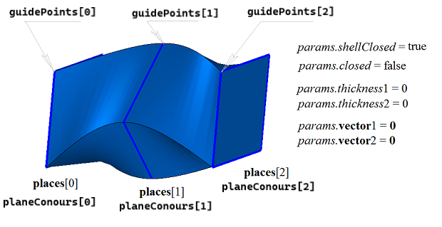
Fig. 12
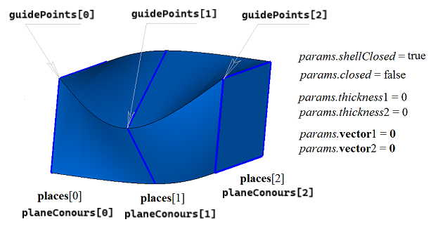
Fig. 13
Fig. 14 shows two 2D contours and a spine curve spine that will serve as a guide for constructing a body by planar sections:
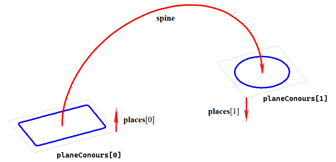
Fig. 14
Fig. 15 shows a closed body constructed by planar sections and spine curve shown in Fig. 14:
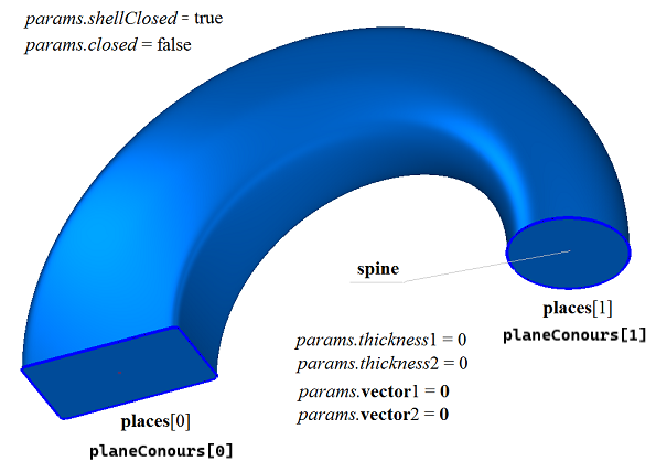
Fig. 15
Fig. 16 shows a closed thin-walled body constructed by planar sections and spine curve shown in Fig. 14:
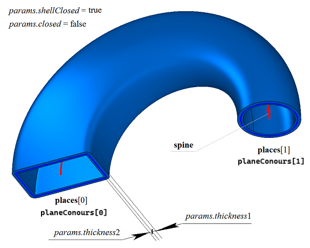
Fig. 16
Fig. 17 shows a non-closed body constructed by planar sections and spine curve shown in Fig. 14:
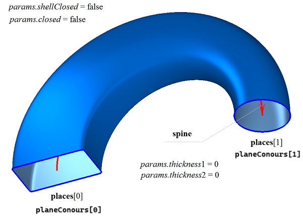
Fig. 17
The body construction function by sections LoftedSolid() adds the MbCurveLoftedSolid builder to the history of the constructed body, which contains all the data required for constructing the body. The MbCurveLoftedSolid builder is declared in the cr_lofted_solid.h file.
In the test.exe test application, body construction by planar sections is performed by the “Create→Solid→Based on curves→Lofting” and “Create→Solid→Based on curves→Lofting with a spine and guide curves” menu commands.