Rounding Off Body Vertices and Edges
The function
MbResultType FilletSolid(       MbSolid &               solid,
                                MbeCopyMode             sameShell,
                          const MbShellFilletValues &   filletParams,
                                c3d::SolidSPtr &        result,
                                IProgressIndicator *    progInd = nullptr );
replaces the specified edges of a source body with faces that smoothly connect the adjacent faces of the specified edges. In a cross-section, the connecting faces can have the shape of a circle arc, an ellipse, a hyperbola, or a parabola.
Methods of rounding the body edges:
Rounding the specified body edges with a constant radius;
Rounding the vertices and the edges adjacent to them with a constant radius (three edges must meet at a vertex);
Rounding the specified body edges with a variable radius defined by MbEdgeFunction.function.
The parameters of a cross-section can vary according to a given law. The method of constructing a fillet is defined by the set of parameters in the filletParams object.
The input parameters of the function are:
solid – a source body whose edges are to be processed;
sameShell – the mode of copying the source body;
filletParams – the construction parameters.
The output parameter of the function is the constructed body result.
The function returns a result code of the operation from the MbResultType enumeration.
The function is declared in the action_solid.h file.
Rounding Edges with a Constant Radius
When rounding edges with a constant radius, the following constructor is defined in the MbShellFilletValues class to initialize filletParams objects with the operation parameters:
MbShellFilletValues(       c3d::EdgesSPtrVector      initCurves,
                           c3d::FacesSPtrVector &    initBounds,
                     const SmoothValues &            params,
                     const MbSNameMaker &            names )
: MbShellChamferParams( initCurves, params, names )
, _initBounds( initBounds ) {}
where
initCurves – a set of body edges to be rounded;
initBounds – a set of faces for trimming the ends;
params – an object that contains parameters of edge rounding;
names – a name maker.
The fillet construction parameter params contains information about the shape and the method of conjugation of the adjacent faces of the processed edges, see Fig. 1. The SmoothValues class is described in the op_shell_parameter.h file.
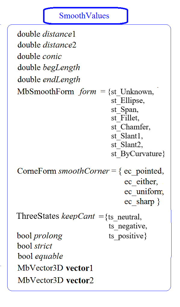
Fig. 1
distance1 – the curvature radius on the first surface;
distance2 – the curvature radius on the second surface;
conic – the shape coefficient of the conjugation surface, takes the values 0, 0.05…0.95 (0 means an arc of a circle or an ellipse);
begLength – the distance from the start of the fillet to the stop point (UNDEFINED_DBL means there is no stop);
endLength – the distance from the end of the fillet to the stop point (UNDEFINED_DBL means there is no stop);
form – the type of conjugation (fillet) from the MbeSmoothForm enumeration;
smoothCorner – the method of processing corners where three edges meet;
prolong – the flag of extending the fillet along tangent edges;
keepCant – the parameter for automatic detection of preserving an edge (ts_neutral), preserving a face (ts_negative), or preserving an edge (ts_positive);
strict – the construction strictness flag: if false, round at least what is possible;
equable – the flag of inserting a toroidal surface in the corners of the junction of the conjugation surface (for sheet-metal stamping);
vector1 – the normal vector to the plane by which the fillet is cut off at the start of the chain;
vector2 – the normal vector to the plane by which the fillet is cut off at the end of the chain.
The fillet type is controlled by the form parameter. For edge rounding, the form parameter values st_Ellipse, st_Fillet and st_Span are used.
If form = st_Fillet, the function constructs a fillet surface with the given radii defined by the distance1 and distance2 parameters. Fig. 2 shows a fillet with given radii of an edge connecting two cylindrical surfaces:
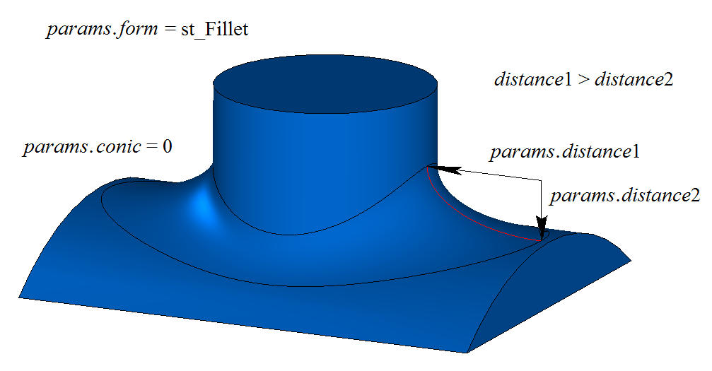
Fig. 2
If distance1 = distance2 and conic = 0, the fillet surface is constructed by moving a sphere that is tangent to the two faces adjacent to the edge being rounded. The support edges of the conjugation face pass through the points of tangency of the sphere and the corresponding adjacent face. A cross-section of the conjugation face is an arc of a circle. Fig. 3 shows a fillet with equal specified radii of an edge connecting two cylindrical surfaces:
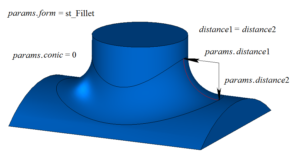
Fig. 3
The conic coefficient controls the shape of the fillet surface. If conic = 0 (the _ARC_ macro), a cross-section of the conjugation surface has the shape of an arc of a circle or an ellipse with the specified radii. In addition to zero, the shape coefficient can take values from 0.05 to 0.95.
If conic = 0.5, a cross-section of the fillet face is an arc of a parabola.
If conic < 0.5, a cross-section of the fillet face is an arc of an ellipse.
If conic > 0.5, a cross-section of the fillet face is an arc of a hyperbola.
Figs. 4, 5 show fillets with equal radii of an edge connecting two cylindrical surfaces and with different shape coefficients:
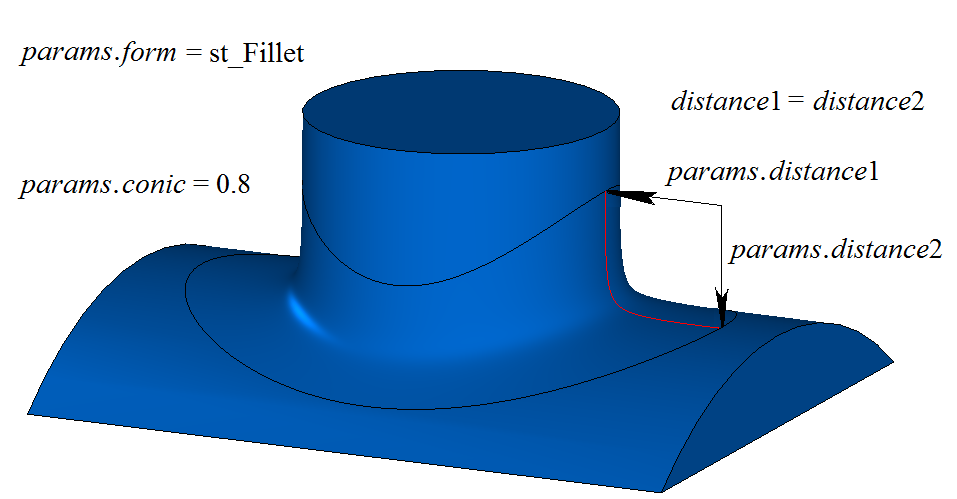
Fig. 4
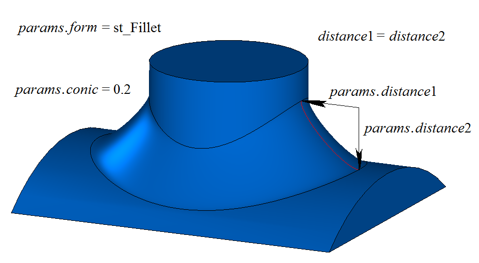
Fig. 5
If form = st_Span, the function constructs a fillet surface with a given chord. The distance1 and distance2 parameters are equal and define the distance between the support edges of the conjugation face. A cross-section of the fillet face is an arc of a circle. In the general case, in each cross-section of the fillet face the radius of the arc is different, and the distance1 and distance2 parameters are equal to the chord of the circular arc. Fig. 6 shows a fillet with a given chord of an edge connecting two cylindrical surfaces:
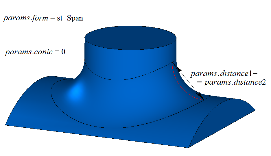
Fig. 6
Fig. 7 shows a fillet with a given chord of an edge connecting two cylindrical surfaces and a nonzero shape coefficient:
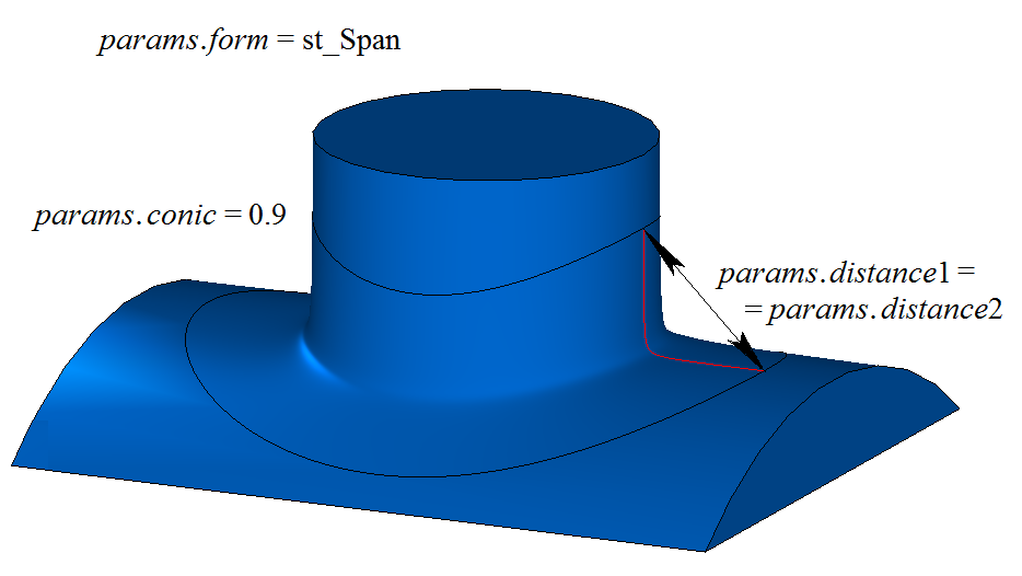
Fig. 7
Fig. 8 shows an example of stopping a fillet at the begLength distance from the initial vertex and at the endLength distance from the terminal vertex of the processed edge. If conjugation is not to be stopped, the begLength and endLength distances must be set to UNDEFINED_DBL. By default, the fillet is stopped by faces that are perpendicular to the edge being rounded. You can override the fillet stopping behavior by using the vector1 vector as the normal of the stop face at the start of the conjugation and the vector2 vector as the normal of the stop face at the end of the conjugation.
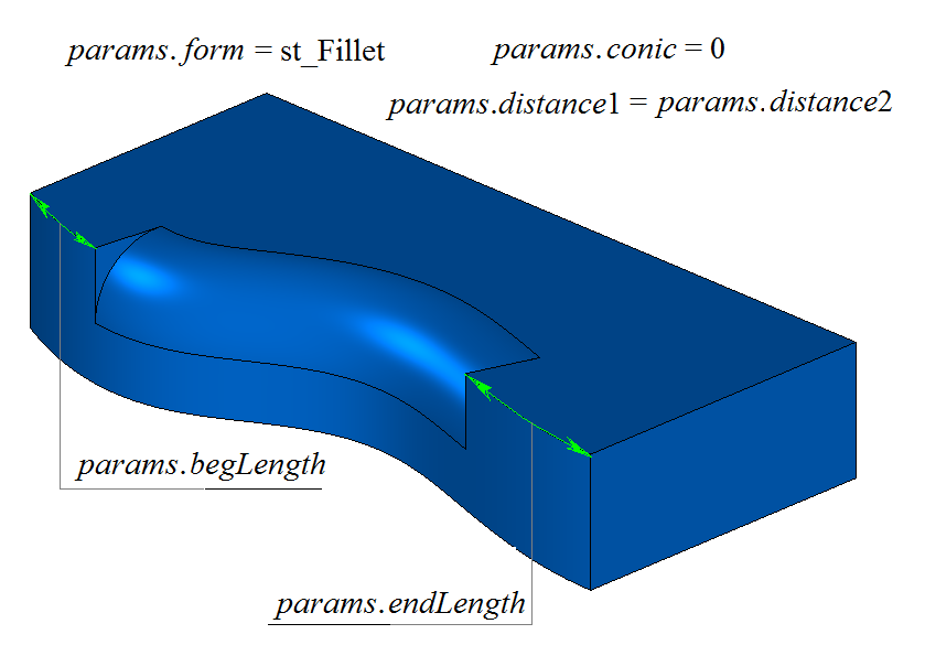
Fig. 8
Using the body in Fig. 9 as an example, we will demonstrate how the prolong and keepCant flags work when rounding the edge highlighted in the figure:
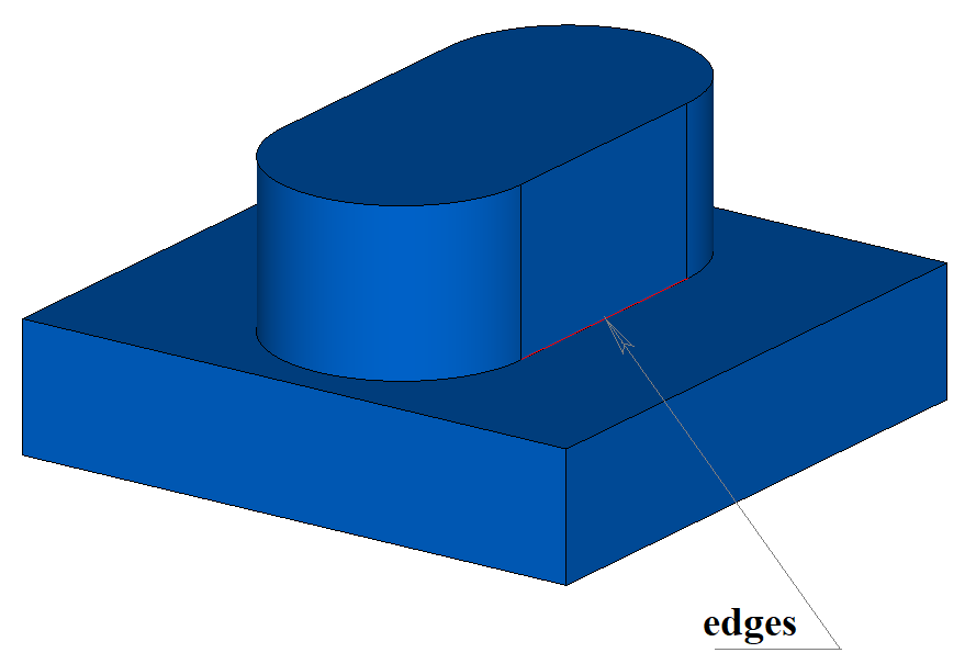
Fig. 9
The prolong flag specifies which body edges must be processed. If prolong = false, only the edges specified in the initCurves container are processed, see Fig. 10:
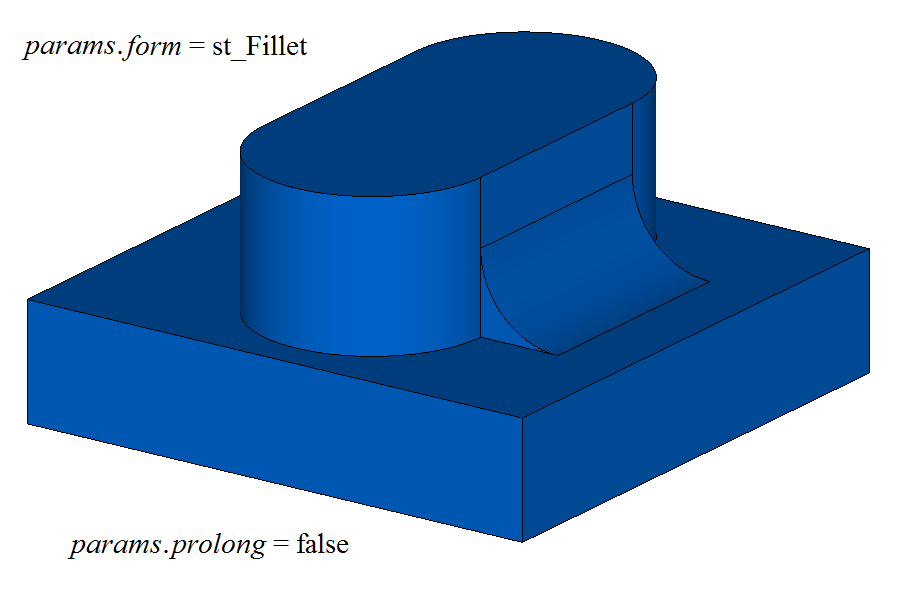
Fig. 10
If prolong = true, the edges specified in the initCurves container as well as the edges that are smoothly connected to them are processed, see Fig. 11:
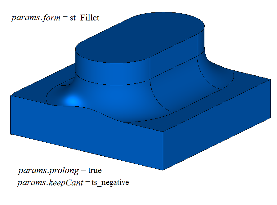
Fig. 11
The keepCant parameter controls the processing of cases where the support edges of the conjugation face go beyond the boundary of an adjacent face.
If keepCant = ts_negative, when the support edge of the conjugation face goes beyond the boundary of an adjacent face across a sharp edge, the conjugation face does not change its shape but is “cut off” by the neighboring face, as shown in Fig. 11.
If keepCant = ts_positive, when the support edge of the conjugation face goes beyond the boundary of an adjacent face across a sharp edge, the conjugation face changes its shape and follows the boundary with its support edge, keeping the boundary unchanged, as shown in Fig. 12:
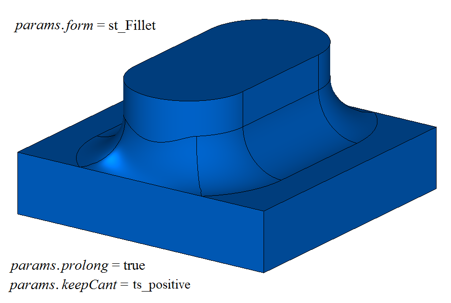
Fig. 12
If keepCant = ts_neutral, when the support edge of the conjugation face goes beyond the boundary of an adjacent face across a smooth edge, the conjugation face replaces the adjacent face with a neighboring one, changing its shape in this region, see Fig. 13:
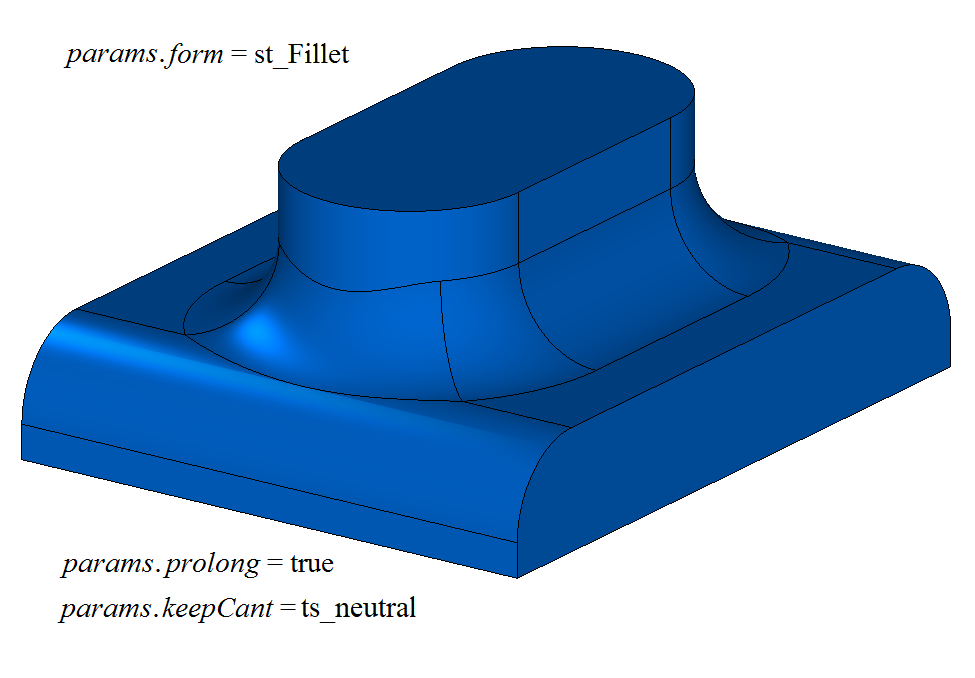
Fig. 13
Fig. 14 shows the filleting of four edges performed by a single function call with the equable flag set to false (no toroidal surface in the corners of the junction):
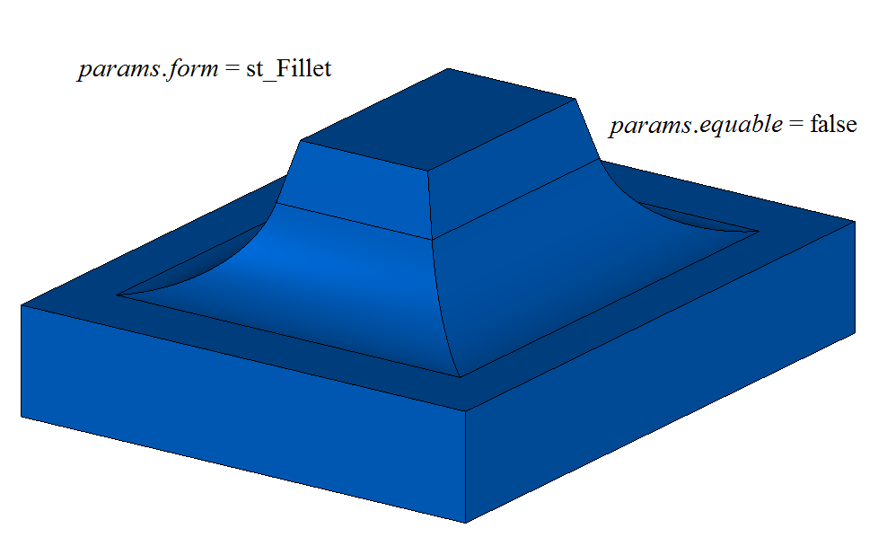
Fig. 14
Fig. 15 shows the filleting of four edges performed by a single function call with the equable flag set to true, which indicates that a toroidal surface must be inserted in the corners of the conjugation surfaces:
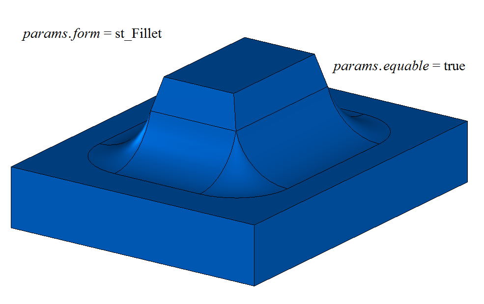
Fig. 15
When constructing a fillet of three edges that meet at one vertex, the smoothCorner parameter defines how suitcase-like corners are processed. If smoothCorner = ec_pointed, corners where three edges of the same convexity meet are not processed (see Fig. 16):
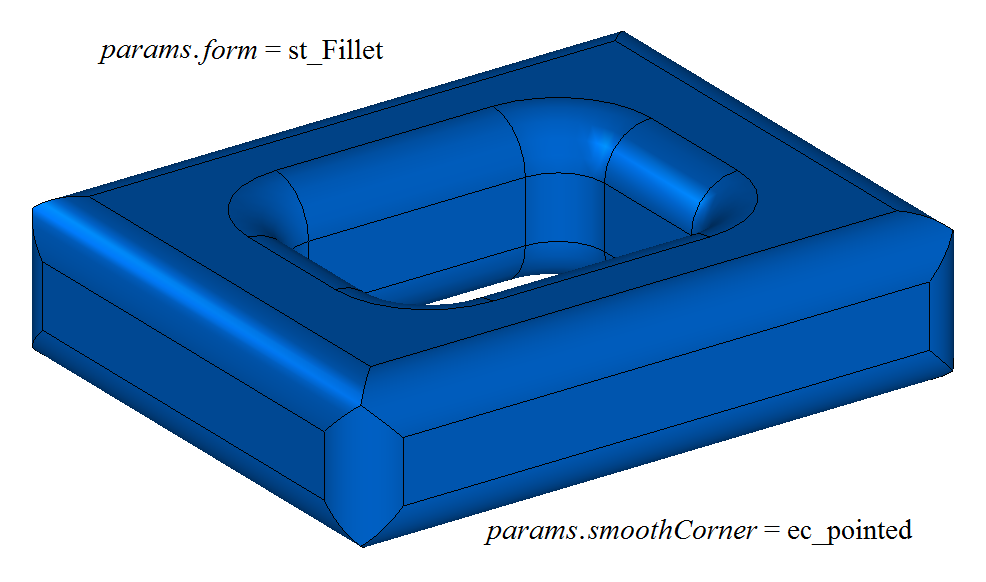
Fig. 16
If smoothCorner = ec_uniform, corners where three edges of different convexity meet are processed in the same way: if at a point two convex (concave) edges and one concave (convex) edge meet, the two convex (concave) edges are processed first (see Fig. 17):
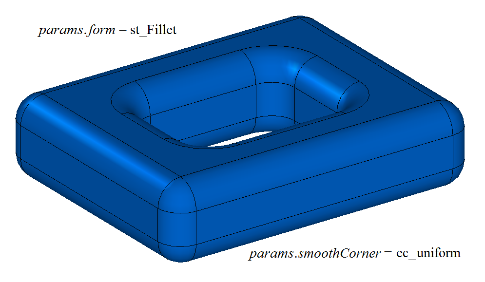
Fig. 17
If smoothCorner = ec_sharp, corners where three edges of different convexity meet are processed in the same way, as shown in Fig. 18. If at a point two convex (concave) edges and one concave (convex) edge meet, the convex (concave) edges are processed first.
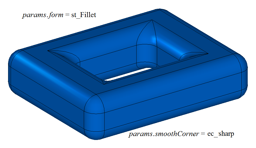
Fig. 18
If smoothCorner = ec_either, corners where three edges of different convexity meet can be processed in different ways: three edges meeting at one point are processed in the order of their internal numbering, regardless of whether they are convex or concave.
In an ambiguous situation at the ends of a conjugation face, the initBounds parameter with the solid body faces that must be used to trim the conjugation faces can be used. An example of using the initBounds parameter is shown in Figs. 19 and 20:
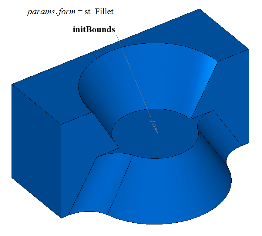
Fig. 19
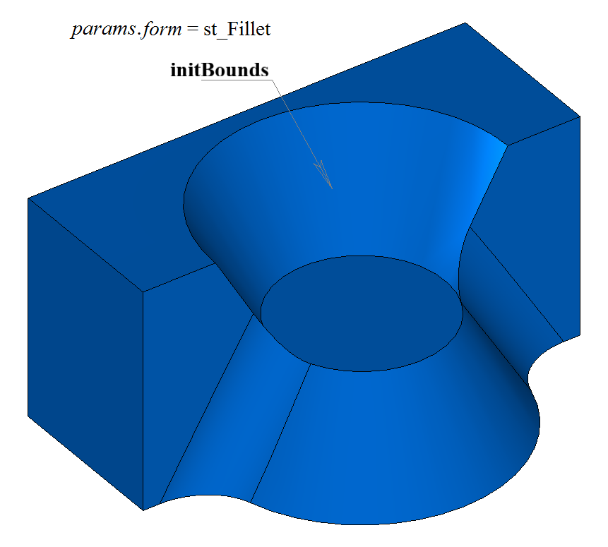
Fig. 20
The initBounds parameter can be used to stop conjugation faces at the start and at the end. In this case, the faces defined by the initBounds parameter must belong to the source body solid.
Fig. 21 shows a model for which it is required to construct fillets of the specified edges that completely embrace a hole and a protrusion:
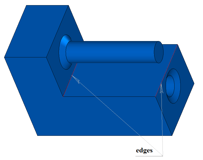
Fig. 21
The result of constructing a fillet that bypasses obstacles is shown in Fig. 22:
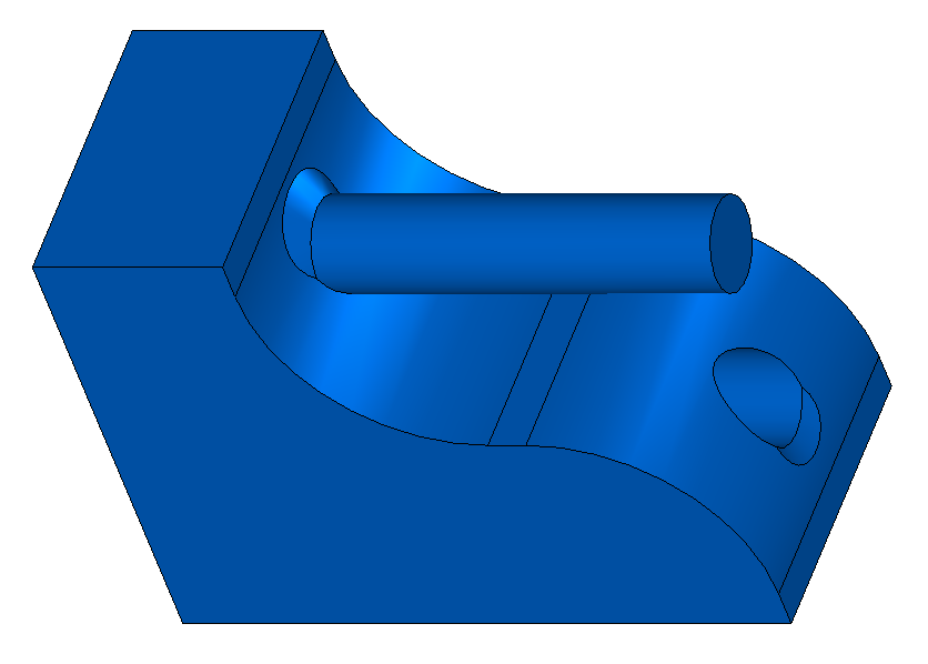
Fig. 22
Fig. 23 shows an example of simultaneously rounding a group of six edges that meet at a common vertex:
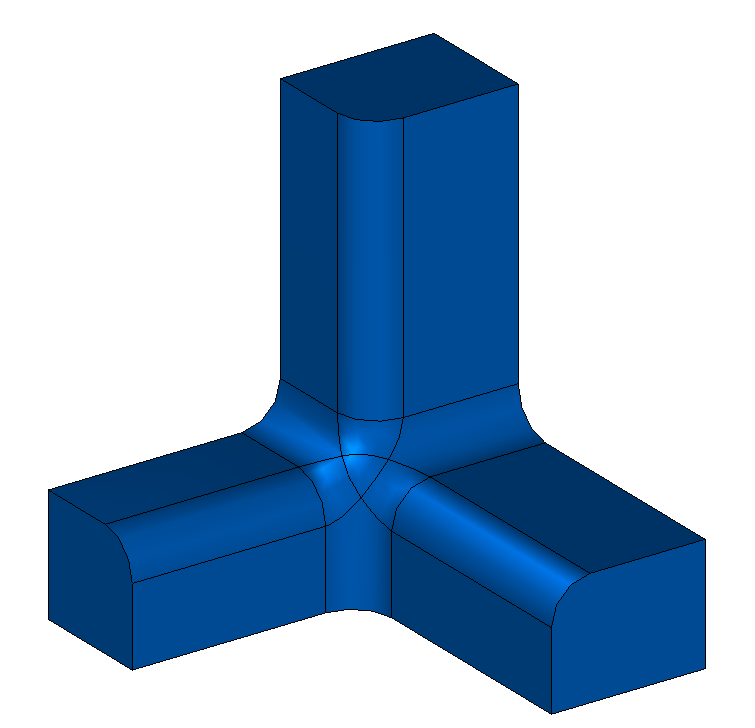
Fig. 23
Fig. 24 shows an example of rounding several groups of four edges that meet at common vertices. A specific feature of the fillet is that the groups are interconnected and can only be processed simultaneously. The source body for the body shown in the figure is obtained by subtracting four cylinders whose axes coincide with the cube diagonals from a cube.
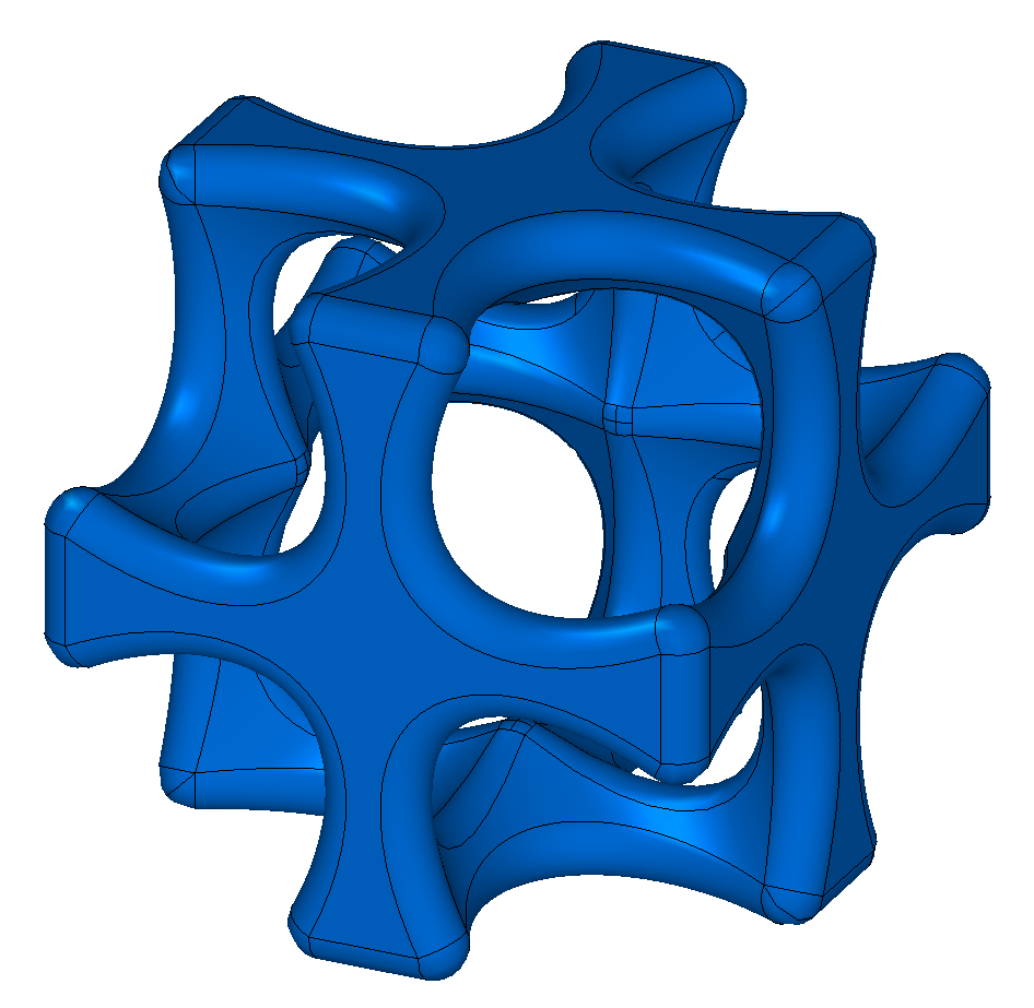
Fig. 24
When in the fillet construction methods the distance1 and distance2 parameters are not equal and several edges are specified for processing, it is hard to understand which parameter corresponds to which object. In such a situation, auxiliary methods are suggested: SmoothPhantom(), SmoothSequence(), and SmoothPositionData(), which are declared in the action_phantom.h file.
The SmoothPhantom() function constructs simplified surfaces to simulate future fillets.
The SmoothSequence() function constructs edge sequences, to which smoothly connected edges to be processed together can optionally be added.
The SmoothPositionData() function calculates a triple of fillet support points that make it possible to evaluate the specified fillet parameters.
Usually, using these functions, a certain phantom is drawn, which makes it possible to understand what the result of the operation will be and to change the parameters if necessary.
Before constructing fillets, the processed edges are sorted, and if necessary or on demand, smoothly connected edges are added to them, and sequences of smoothly connected edges are created from the edges.
The distance1 and distance2 parameters are associated with the first and the second surfaces and, accordingly, with the intersection curve of the first edge in the sequence of smoothly connected edges.
The surfaces can be obtained by the intersection curve functions GetCurveOneSurface() and GetCurveTwoSurface().
The distance1 and distance2 of the first edge define the parameters for the other edges of each sequence. Thus, if for the first edge the pointer edge→GetIntersectionCurve().GetSurfaceOne() is equal to the pointer edge→GetFacePlus()→GetSurface().GetSurface(), then, when constructing a fillet, distance1 will correspond to the radius for the facePlus face and distance2 will correspond to the radius for the faceMinus face of the first edge in the sequence.
When constructing edge fillets, the function adds the MbFilletSolid builder to the body log; this builder is declared in the cr_fillet_solid.h file.
In the test application test.exe, edge processing of a body is performed by the menu commands “Create → Solid → By edge processing → Fillet with radius” and “Create → Solid → By edge processing → Fillet by a chord”.
Rounding Edges with a Variable Radius
The function is similar to the one described in the previous subsection and differs from it by the initFunctions parameter. When rounding edges, the conjugation faces in a cross-section can have the shape of a circular arc with a variable radius.
When rounding edges with a variable radius, the following constructor is defined in the MbShellFilletValues class to initialize filletParams objects with the operation parameters:
MbShellFilletValues( const std::vector<MbEdgeFunction> & initFunctions,
                           c3d::FacesSPtrVector &        initBounds,
                     const MbSNameMaker &                names,
                     const SmoothValues &                params )
: MbShellChamferParams( c3d::EdgesSPtrVector(), params, names )
, _initFunctions( initFunctions )
, _initBounds( initBounds ) {}
where
initFunctions – a set of body edges to be rounded with the functions of radius variation;
initBounds – a set of faces for trimming the ends;
params – an object that contains the parameters of edge rounding;
names – a name maker.
The initFunctions parameter contains the processed edges of the solid body and the radius variation functions along an edge. Each element of the initFunctions set consists of a pointer to an edge and a pointer to a scalar function whose values are used to scale the fillet radii distance1 and distance2, see Fig. 25:
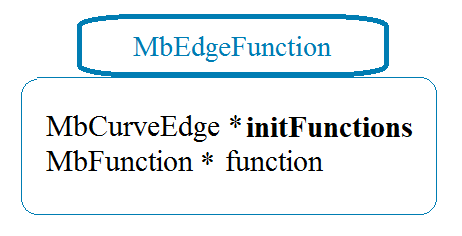
Fig. 25
For rounding edges with a variable radius, the form parameter value st_Fillet is used. For each point of a processed edge, initFunctions[i].initFunctions→Point(t, point), the radii of the fillet surface are equal to the distance1 and distance2 parameters multiplied by the value of the edge function initFunctions[i].function→Value(t).
Fig. 26 shows a fillet with variable radii of an edge of a rectangular prism. If distance1 = distance2 and conic = 0, the fillet surface is constructed by moving a sphere of variable radius that is tangent to the two faces adjacent to the edge being rounded. The support edges of the conjugation face pass through the points of tangency of the sphere and the corresponding adjacent face. A cross-section of the conjugation face is an arc of a circle.
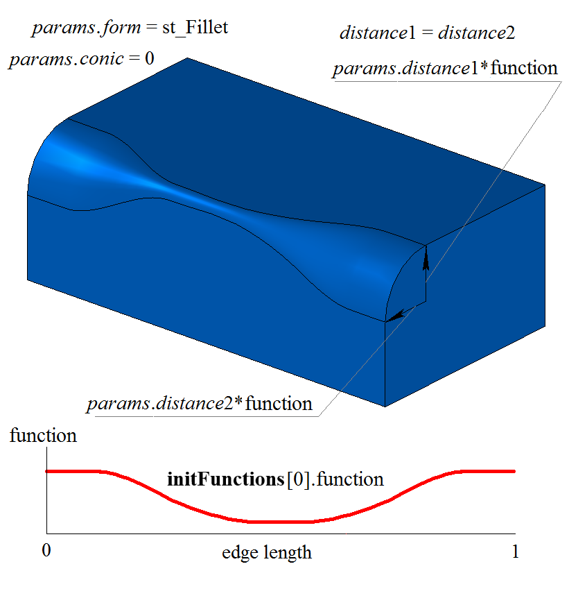
Fig. 26
Fig. 27 shows an elliptic fillet with variable radii of an edge of a rectangular prism:
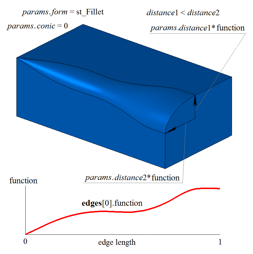
Fig. 27
Figs. 28, 29 show fillets with variable radii of an edge of a rectangular prism and different shape coefficients conic:
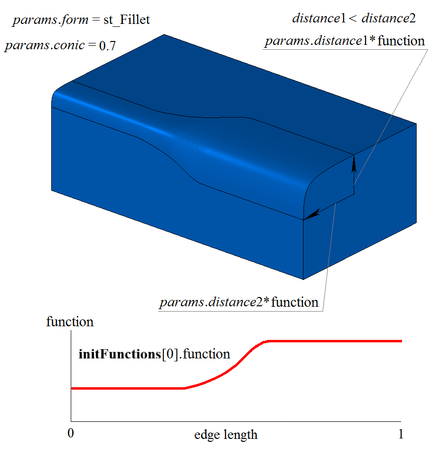
Fig. 28
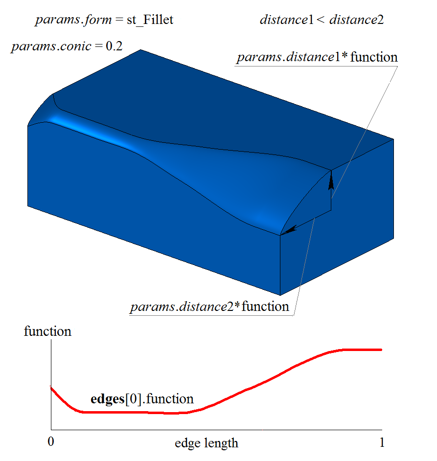
Fig. 29
Fig. 30 shows an example of stopping a fillet at the begLength distance from the initial vertex and at the endLength distance from the terminal vertex of the processed edge. When specifying the parameters of stopping a fillet, the fillet radius variation method is defined for the entire edge. If conjugation is not to be stopped, the begLength and endLength distances must be set to UNDEFINED_DBL.
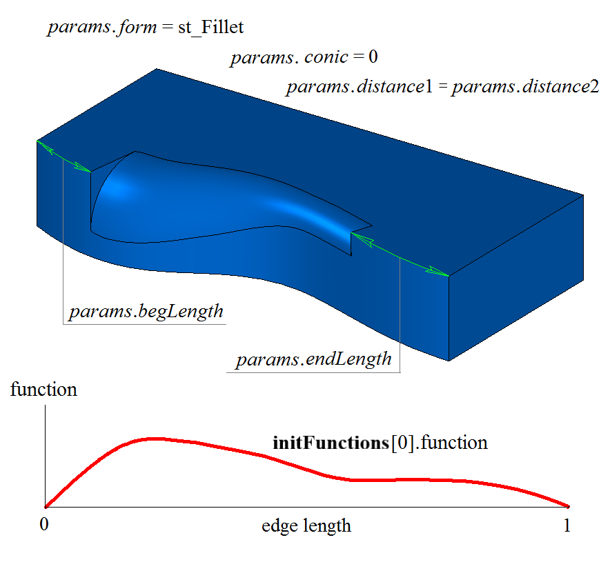
Fig. 30
For continuation edges of a fillet, the radius variation function takes a constant value equal to the value of the function at the end of the previous smoothly connected edge. Fig. 31 shows the source body, the edges to be rounded, and the radius variation function for the specified edges:
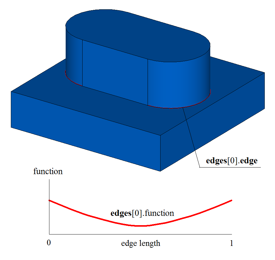
Fig. 31
Fig. 32 shows the result of the function for the source body. The figure shows that at the ends the radius variation function is chosen so as to provide smooth conjugation with a neighboring fillet face:
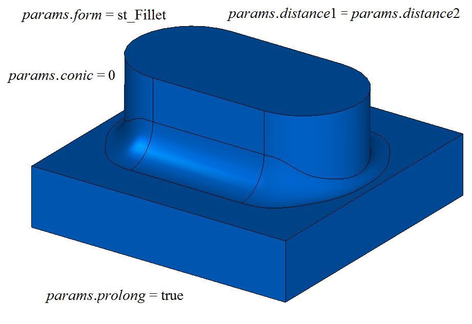
Fig. 32
In the test application test.exe, edge processing of a body with a variable radius is performed by the menu command “Create→Solid→By edges processing→Variable fillet”.
Rounding Vertices and Adjacent Edges with a Constant Radius
When rounding vertices and the edges adjacent to them with a constant radius, the following constructor is defined in the MbShellFilletValues class to initialize filletParams objects with the operation parameters:
MbShellFilletValues(       c3d::EdgesSPtrVector &    initCurves,
                           c3d::FacesSPtrVector &    initBounds,
                           c3d::VerticesSPtrVector & initVertices,
                     const CornerValues &            cornerData,
                     const SmoothValues &            params,
                     const MbSNameMaker &            names )
: MbShellChamferParams( initCurves, params, names )
, _initBounds  ( initBounds )
, _initVertices( initVertices )
, _cornerData  ( cornerData ) {}
where
initCurves – a set of body edges to be rounded;
initBounds – a set of faces for trimming the ends;
initVertices – a set of vertices to be rounded;
cornerData – an object that contains vertex rounding parameters;
params – an object that contains parameters of edge rounding;
names – a name maker.
The fillet construction parameter params contains information about the shape and the method of conjugation of the adjacent faces of the processed edges (see Rounding Edges with a Constant Radius).
The vertex rounding parameters cornerData for a vertex where three edges meet contain the information required to perform the operation, see Fig. 33. The CornerValues class is described in the op_shell_parameter.h file.
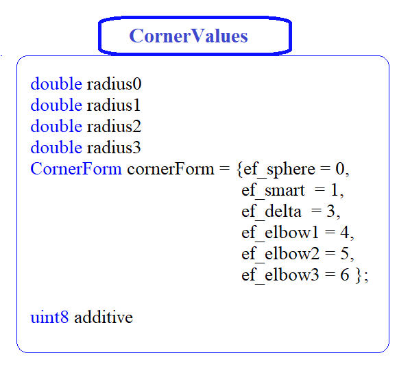
Fig. 33
radius0 – the radius of the sphere at the vertex;
radius1 – the radius of the first edge of the vertex;
radius2 – the radius of the second edge of the vertex;
radius3 – the radius of the third edge of the vertex;
cornerForm – the method of rounding a vertex where three edges meet;
additive – an offset in the numbering of the vertex edges (an increment to an edge number).
The vertex rounding type is controlled by the cornerForm parameter. For vertex rounding, the following cornerForm parameter values are used:
ef_sphere – rounding a vertex with a spherical surface;
ef_smart – rounding a vertex with a smooth surface;
ef_delta – rounding a vertex with a triangular surface;
ef_elbow1 – rounding a vertex with a quadrilateral surface (the fourth side is opposite the first edge of the vertex);
ef_elbow2 – rounding a vertex with a quadrilateral surface (the fourth side is opposite the second edge of the vertex);
ef_elbow3 – rounding a vertex with a quadrilateral surface (the fourth side is opposite the third edge of the vertex).
If cornerForm = ef_sphere, vertices where three edges of different convexity meet are rounded with a spherical surface, as shown in Fig. 34:
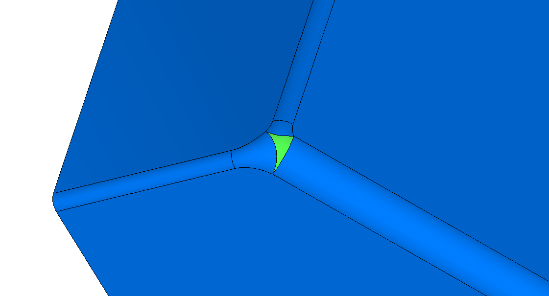
Fig. 34
If cornerForm = ef_smart, vertices where three edges of different convexity meet are rounded with a smooth surface, as shown in Fig. 35:
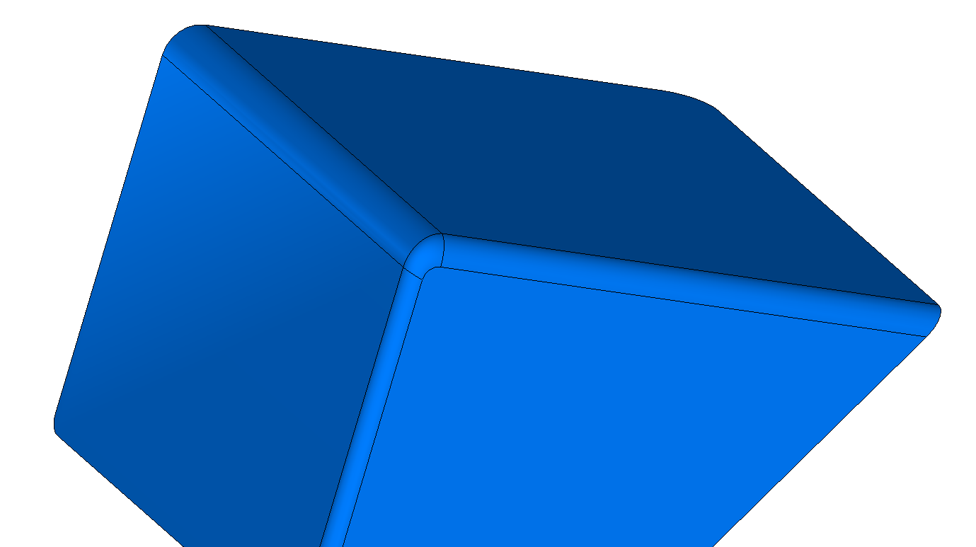
Fig. 35
If cornerForm = ef_delta, vertices where three edges of different convexity meet are rounded with a triangular surface, as shown in Fig. 36:
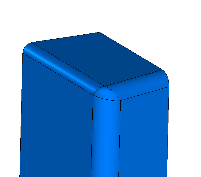
Fig. 36
If cornerForm = ef_elbow2, vertices where three edges of different convexity meet are rounded with a quadrilateral surface whose fourth side is opposite the second edge of the vertex, as shown in Fig. 37:
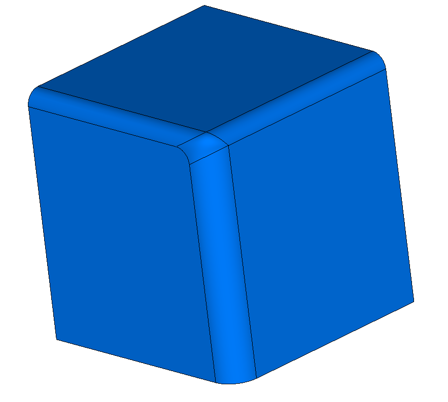
Fig. 37
In the test application test.exe, rounding vertices and the edges adjacent to them with a constant radius is performed by the menu command “Create→Solid→By vertices processing→Vertices fillet”.