Triangulation Calculation Control
The MbStepData structure is used as input to the polygonal representation construction methods, and is shown in Fig. 1:
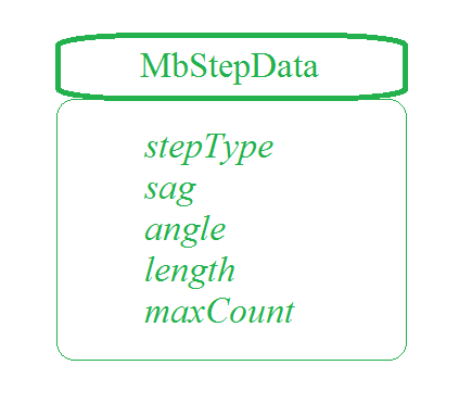
Fig. 1
The MbStepData structure is declared in the mb_data.h file. The MbStepData structure contains the following data:
unsigned char stepType – field that defines the method for calculating the parameter increment;
double sag – maximum allowable deviation by sag;
double angle – maximum allowable deviation by the angle of tangents or normals;
double length – maximum allowable distance between neighboring points;
unsigned int maxCount – maximum number of cells in a row or column of the triangulation grid.
The MbStepData structure controls the density of the polygonal object mesh and contains data used to compute the parameter step when moving along curves and surfaces of the model. The stepType field defines the method for computing the parameter increment when moving along a curve or surface and can contain masks of the MbeStepType enumeration declared in the mb_enum.h file:
ist_SpaceStep – for geometric shape visualization;
ist_DeviationStep – for construction operations;
ist_MetricStep – for 3D printers;
ist_ParamStep – for visualizing the geometric shape of objects with texture binding to the surface parameters;
ist_CollisionStep – for detecting collisions of model elements;
ist_MipStep – for calculating inertial characteristics.
The sag parameter limits the parameter step of a curve or surface based on the maximum allowable deviation of the polygonal object from the original by sag. The angle parameter limits the parameter step of a curve or surface based on the maximum allowable deviation of the polygonal object from the original by the angular deviation of curve tangents or surface normals at neighboring points at the step distance. The length parameter limits the parameter step of a curve or surface based on the maximum allowable size of a polygonal object element – the side of a triangle or a polygon segment. The maxCount parameter limits the parameter step of a curve or surface based on the maximum allowable number of divisions in a row or column of the triangulation grid.
The MbFormNote structure is also used as input to the polygonal representation construction methods, and is shown in Fig. 2:
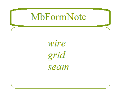
Fig. 2
The MbFormNote structure is declared in the mb_data.h file. The MbFormNote structure contains the following data:
bool wire – polygonal object construction flag;
bool grid – polygonal object construction flag;
bool seam – seam edge usage flag.
The MbFormNote structure defines how the polygonal object is constructed: if wire == true, the polygonal object is filled with polyline segments, if grid == true, the polygonal object is filled with triangulations. The seam parameter defines how seams are represented in the polygonal object: if seam == true, triangulation is not closed at seams and seam edges are treated as ordinary edges – their points are considered boundary points in the triangulation and polygons are constructed for them; if seam == false, triangulation is closed at seams and seam edges are ignored – triangulations are constructed as closed, and polygons for seams are not constructed.