Constructing a Revolution Body
The function
MbResultType RevolutionSolid( const MbSweptData &           sweptData,
                              const MbAxis3D &              axis,
                              const RevolutionValues &      params,
                              const MbSNameMaker &          operNames,
                                    RPArray<MbSNameMaker> & contoursNames,
                                    MbSolid *&              result );
constructs a revolution body.
The input parameters of the function are:
sweptData – data on generatrix curves;
axis – axis of revolution;
params – an object that contains revolution parameters;
operNames – the operation name maker;
contoursNames – the name makers of the segments of the generatrix contour.
The output parameter of the function is the constructed body (shell) result.
The function returns an operation result code from the MbResultType enumeration (see mb_operation_result.h).
The function is declared in the action_solid.h file.
A revolution body belongs to a type of swept bodies obtained by moving a generatrix curve along a guide curve. The guide curve of a revolution body is a circle or its arc. The revolution body is constructed by rotating one or several curves around the axis.
The sweptData parameter contains information about the generatrix curves. The MbSweptData and RevolutionValues classes are described in the op_swept_parameter.h file. The generatrix curves may represent two-dimensional contours on a surface or contours3D in space. In a special case, the surface may represent a plane. The orientation of the contours may be arbitrary. The contours may be nested inside each other.
Rotation of curves may be performed in the forward direction relative to the axis axis, in the reverse direction relative to the axis axis, and in both directions. Rotation in the forward direction is performed counterclockwise when looking towards the axis axis. The construction parameters in each direction are defined by MbSweptSide objects.
The params parameter contains two MbSweptSide class objects – side1 and side2, which store revolution parameters in the forward and reverse directions.
The revolution method is defined in the way field of the MbSweptSide class object:
If way = sw_scalarValue, the rotation is performed through the angle scalarValue in the side1 or side2 direction. The rotation angle is defined in radians.
If way = sw_surface, the rotation is performed up to the side1.surface or side2.surface surface if side1.distance equals zero or side2.distance equals zero, respectively.
If way = sw_surface and distance is not equal to zero, the rotation is performed up to a surface equidistant from side1.surface or up to a surface equidistant from side2.surface, respectively.
If way = sw_shell, the rotation is performed up to the nearest object (body) in the side1 or side2 direction.
The params.thickness1 and params.thickness2 parameters define the wall thickness of a thin-walled body. The params.thickness1 parameter specifies the offset outward from the generatrix curve, and the params.thickness2 parameter specifies the offset inward from the generatrix curve.
The params.shellClosed parameter controls whether the constructed body is closed.
The params.checkSelfInt parameter indicates the need to check the construction result for self-intersection. By default, params.checkSelfInt = false, and the check is not performed.
The params.shape parameter controls the shape of the constructed body. If params.shape = 1, the constructed body has torus topology; if params.shape = 0, the constructed body has sphere topology. If the generatrix is an open planar curve and the axis of revolution lies in the plane of the curve, then it is possible to construct a revolution body with sphere-type topology. In this case, the generatrix is extended up to the axis of revolution.
Fig. 1 shows the data used in the construction and the inheritance scheme of revolution body construction parameters RevolutionValues & params.
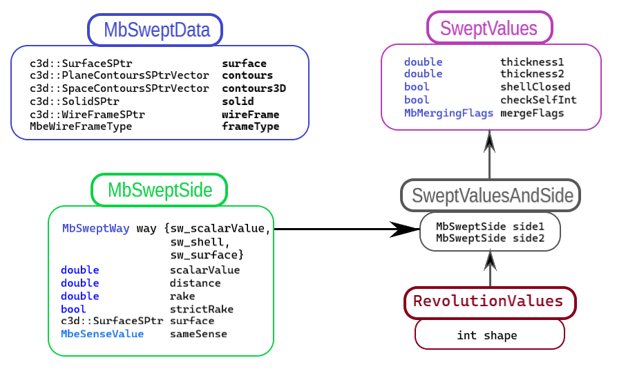
Fig. 1
The operNames and contoursNames parameters provide naming of faces, edges, and vertices of the constructed body.
Fig. 2 shows a two-dimensional contour contour, a planar surface surface (MbPlane), and a revolution axis axis.
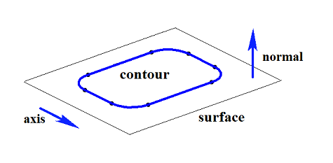
Fig. 2
Fig. 3 shows a closed body constructed by rotation using the specified parameters of the contour shown in Fig. 2.
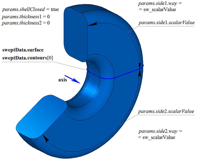
Fig. 3
Fig. 4 shows a closed thin-walled body constructed by rotation using the specified parameters of the contour shown in Fig. 2.
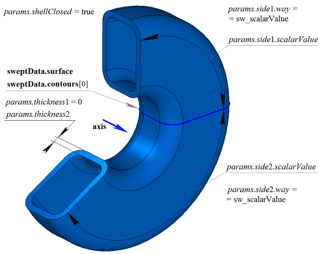
Fig. 4
Fig. 5 shows an open body constructed by rotation using the specified parameters of the contour shown in Fig. 2. The construction parameters of the body shown in Fig. 3 differ from those of the body shown in Fig. 5 only by the params.shellClosed value.
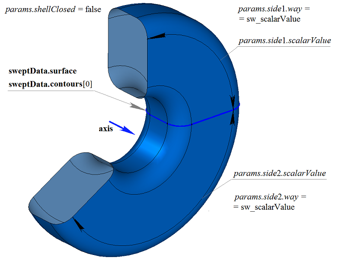
Fig. 5
Fig. 6 shows a two-dimensional contour contour, a planar surface surface (MbPlane) and two surfaces surface1 and surface2 that will be used in the revolution body construction. For the construction, the surface1 and surface2 surfaces must completely cover the path of contour motion in the corresponding direction. At the same time, the params.thickness1 and params.thickness2 parameters must be taken into account. The revolution body is cut by the specified surfaces (if params.side1.distance or params.side2.distance equal zero) or by surfaces equidistant from them (if params.side1.distance or params.side2.distance are not equal to zero).
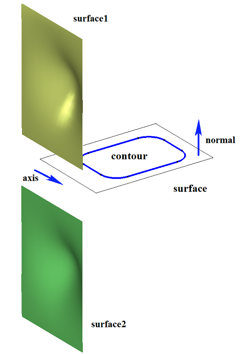
Fig. 6
Fig. 7 shows a body constructed by rotation of the contour shown in Fig. 6, with the “Up to surface” options (params.side1(2).way = sw_surface), where surface1 and surface2 are specified.
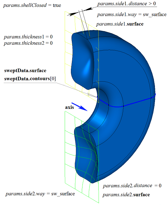
Fig. 7
Fig. 8 shows a thin-walled body constructed by rotation of the contour shown in Fig. 6, with the “Up to surface” options, where surface1 and surface2 are specified. The revolution body is cut by the specified surfaces.
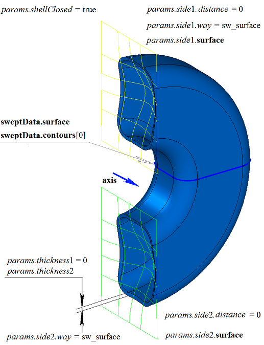
Fig. 8
A two-dimensional contour may lie on a planar or a curved surface. For example, a body can be constructed by rotation of a contour on a curved surface obtained from a loop of one of the faces of a solid body shown in Fig. 9.
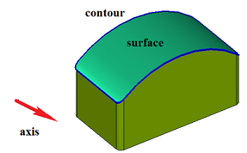
Fig. 9
Fig. 10 shows a closed body obtained by rotation of the contour on the curved surface shown in Fig. 9.
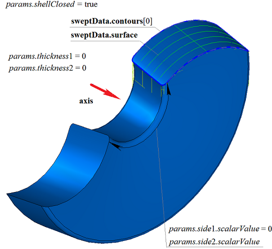
Fig. 10
Fig. 11 shows a closed thin-walled body obtained by rotation of the contour on the curved surface shown in Fig. 9.
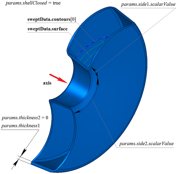
Fig. 11
Fig. 12 shows an open body obtained by rotation of the contour on the curved surface shown in Fig. 9.
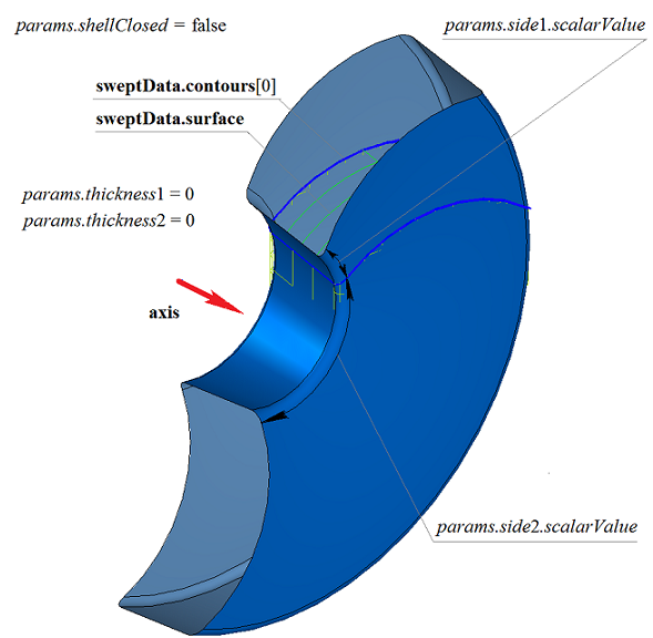
Fig. 12
If multiple non-intersecting two-dimensional contours lie on one surface, the considered function determines outer contours and inner contours nested in them, with potentially multiple nesting levels. Fig. 13 shows multiple non-intersecting two-dimensional contours and a planar surface surface (MbPlane).
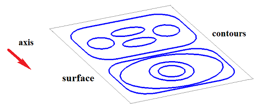
Fig. 13
Fig. 14 shows a closed body consisting of several parts constructed by rotation of the multiple contours shown in Fig. 13.
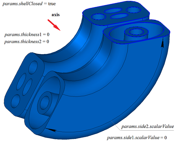
Fig. 14
Fig. 15 shows a closed thin-walled body consisting of several parts constructed by rotation of the multiple contours shown in Fig. 13.
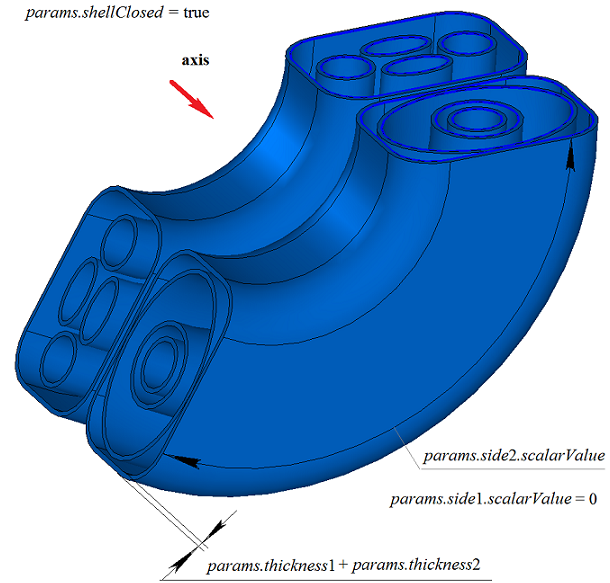
Fig. 15
Fig. 16 shows two three-dimensional contours.
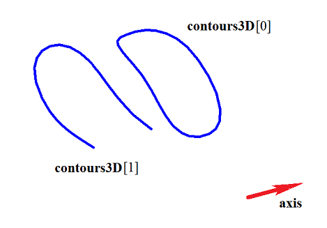
Fig. 16
Fig. 17 shows a doubly connected thin-walled closed body obtained by rotation of the three-dimensional contours shown in Fig. 16.
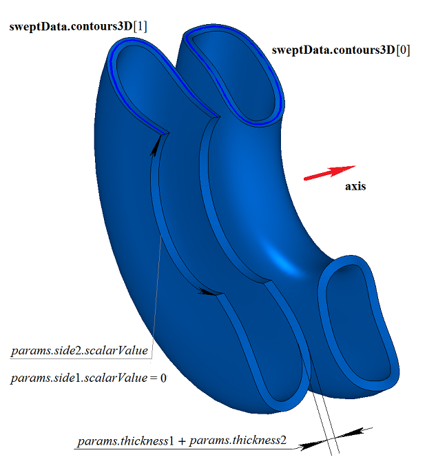
Fig. 17
Fig. 18 shows two open bodies obtained by rotation of the three-dimensional contours shown in Fig. 16. The construction is performed separately for each contour.
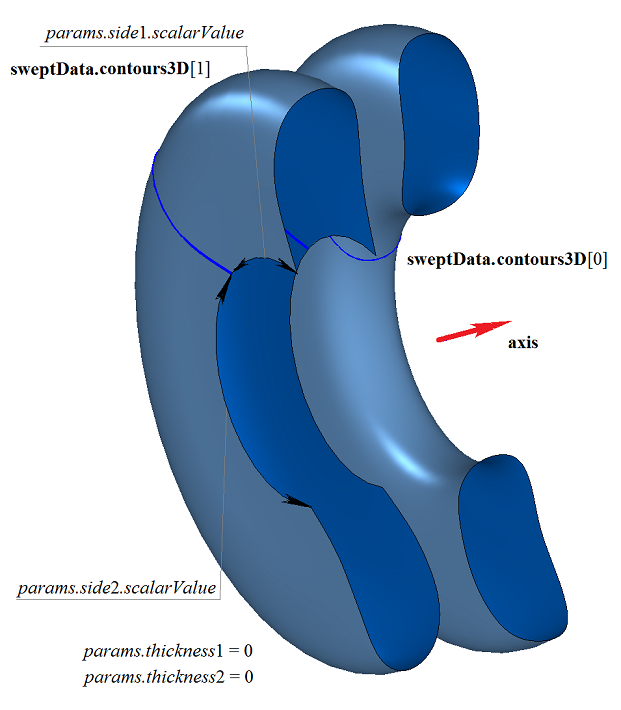
Fig. 18
When constructing a revolution operation up to a construction plane with a degenerate definition domain, the shell is constructed up to the nearest intersection with the specified plane.
If the plane has non-degenerate boundaries, the part of the plane up to which the rotation is constructed is determined by the position of the center of gravity of the contour bounding the plane relative to the projection of the revolution axis onto the plane.
The revolution body construction function RevolutionSolid() adds the MbCurveRevolutionSolid builder to the history of the constructed body, which contains all the data required for constructing the body. The MbCurveRevolutionSolid builder is declared in the cr_revolution_solid.h file.
In the test.exe test application, revolution body construction is performed by the “Create->Solid->Based on curves->Revolution of a curve lying on surface” and “Create->Solid->Based on curves->Revolution of a spatial curve” menu commands.