Constructing an Elementary Body
The function
MbResultType ElementarySolid( const MbElementarySolidParams  & params,
                                    MbElementarySolidResults & results );
constructs an elementary body based on specified points and the type of body being created (see Table 1), as well as on an elementary surface (sphere, torus, cone, cylinder).
The input parameter is an object params of the MbElementarySolidParams class (see the definition in op_shell_parameter.h), which contains the source data for the body creation operation.
The output parameter of the function is the results object of the MbElementarySolidResults class, derived from the MbOperationResults class (see the definition in op_shell_parameter.h), which contains the constructed body and generalized results of the function.
The function returns the result code of the operation from the enumeration MbResultType.
The function is declared in the action_solid.h file.
Constructing an Elementary Body Based on Control Points
For constructing solids based on control points, the MbElementarySolidParams class defines the following constructor to initialize the params object with operation parameters (see op_shell_parameter.h):
MbElementarySolidParams( const ElementaryShellType      & solidType,
                         const c3d::SpacePointsVector   & points,
                         const MbSNameMaker             & operNames );
with parameters:
solidType — the type of body being created;
points — the set of points;
operNames — the operation’s namer.
Different types of bodies require different numbers of control points. Table 1 shows the number of control points required to create a body of solidType type:
Table 1 — Number of control points for various types of elementary bodies
solidType
Body type
Number of control points
et_Sphere
sphere
3 points
et_Torus
torus
3 points
et_Cylinder
cylinder
3 points
et_Cone
cone
3 points
et_Cone
truncated cone
4 points
et_Block
block
4 points
et_Wedge
wedge
4 points
et_Prism
prism
the number of base vertices + 1 point
et_Pyramid
pyramid
the number of base vertices + 1 point
et_Plate
plate
4 points
et_Icosahedron
icosahedron
3 points
et_Polyhedron
polyhedron
3 points
et_Tetrapipe
tetra-pipe
3 points
et_Octapipe
octa-pipe
3 points
For constructing a sphere, points[0] defines the center of the sphere, points[1] defines the direction of the axisZ axis in the sphere’s local coordinate system, points[2] together with the previous points defines the plane of the axisX and axisZ axes in the sphere’s local coordinate system. The distance between points[0] and points[2] defines the radius of the sphere (see Fig. 1):
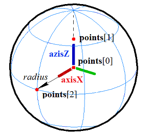
Fig. 1
For constructing a torus, points[0] defines the center of the torus, points[1] defines the direction of the axisX axis in the torus’s local coordinate system, points[2] together with the previous points defines the plane of the axisX and axisZ axes in the torus’s local coordinate system. The distance between points[0] and points[1] defines the major torus radius; the distance between points[1] and points[2] defines the minor torus radius (Fig. 2):
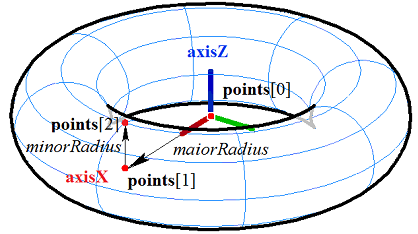
Fig. 2
For constructing a cylinder, points[0] defines the center of the cylinder’s lower base, points[1] defines the center of the cylinder’s upper base and the direction of the axisZ axis in the cylinder’s local coordinate system, points[2] together with the previous points defines the plane of the axisX and axisZ axes in the cylinder’s local coordinate system. The distance between points[0] and points[1] defines the cylinder height; the distance from the axisZ axis to points[2] defines the cylinder radius (Fig. 3):
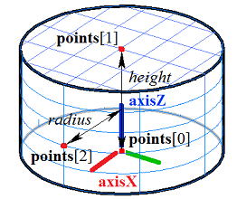
Fig. 3
For constructing a cone, points[0] defines the cone vertex, points[1] defines the center of the cone base and the direction of the axisZ axis in the cone’s local coordinate system, points[2] together with the previous points defines the plane of the axisX and axisZ axes in the cone’s local coordinate system. The distance between points[0] and points[1] defines the cone height. The cone angle is determined from the condition that points[2] lies on the cone’s side surface (Fig. 4):
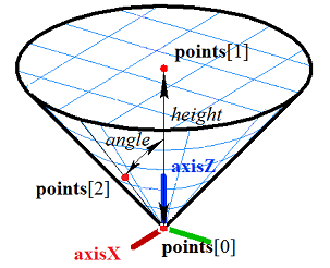
Fig. 4
For constructing a truncated cone, points[0] defines the cone vertex, points[1] defines the center of the larger cone base and the direction of the axisZ axis in the cone’s local coordinate system, points[2] defines the center of the smaller cone base, points[3] together with the previous points defines the plane of the axisX and axisZ axes in the cone’s local coordinate system. The distance between points[1] and points[2] defines the height of the truncated cone. The cone angle is determined from the condition that points[3] lies on the cone’s side surface (Fig. 5):
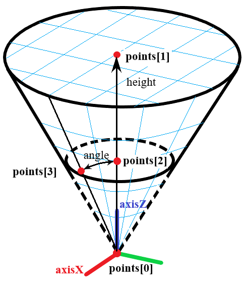
Fig. 5
For constructing a rectangular block, points[0] and points[1] define an edge and two vertices of the block, points[2] together with the previous points defines the plane of the block’s lower base. The block edge parallel to the points[0]– points[1] edge passes through points[2]. points[3] defines the plane of the block’s upper base (Fig. 6):
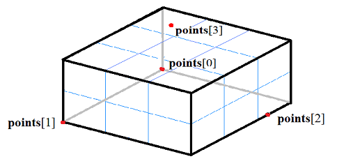
Fig. 6
For constructing a rectangular wedge, points[0] and points[1] define an edge and two vertices of the wedge, points[2] together with the previous points defines the plane of the wedge’s lower base and its vertex. The wedge edge parallel to the points[0]– points[1] edge passes through points[2]. points[3] defines the plane of the wedge’s upper base (Fig. 7):
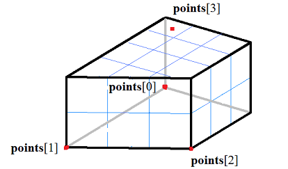
Fig. 7
For constructing a plate with cylindrical ends, points[0] and points[1] define an edge and two vertices of the plate, points[2] together with the previous points defines the plane of the plate’s lower base. The plate edge parallel to the points[0]– points[1] edge passes through points[2]. points[3] defines the plane of the plate’s upper base (Fig. 8):
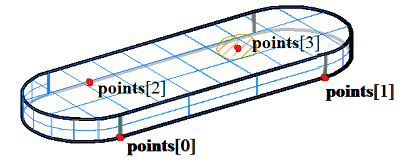
Fig. 8
For constructing a straight prism, points[0], points[1], …, points[n-1] define the base polygon. The distance from the plane of the lower base to the last point points[n] defines the prism height. Fig. 9 shows a straight prism with a pentagonal base:
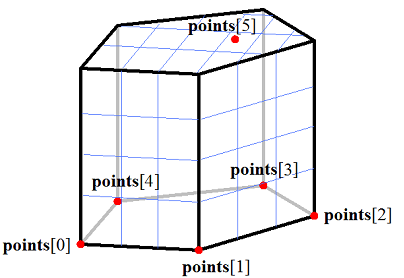
Fig. 9
For constructing a pyramid with a polygon at the base, points[0], points[1], …, points[n-1] define the base polygon; the last point points[n] defines the pyramid vertex. Fig. 10 shows a pyramid with a pentagonal base:
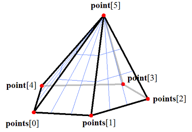
Fig. 10
The base polygon of a prism or pyramid can be arbitrary.
For constructing an icosahedron, points[0], points[1], points[2] define the vertices and planes of all faces of the shape (Fig. 11):
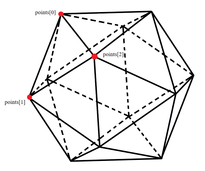
Fig. 11
Constructing an Elementary Body by a Given Surface
For constructing solids based on an elementary surface, use the ElementarySolid() function with the following constructor to initialize the params object with operation parameters (see op_shell_parameter.h):
MbElementarySolidParams( const SPtr<const MbElementarySurface> & surface,
                         const MbSNameMaker                    & operNames );
with parameters:
surface — the elementary surface (sphere, torus, cylinder, cone);
operNames — the operation’s namer.
An elementary surface can be a sphere MbSphere, a torus surface MbTorus, a cylindrical surface MbCylinder, or a conical surface MbCone. Fig. 12 shows a spherical surface and a body constructed on it:
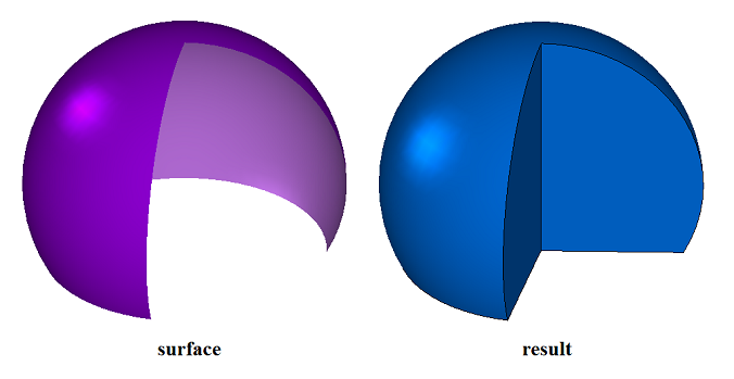
Fig. 12
Fig. 13 shows a torus surface and a body constructed on it:
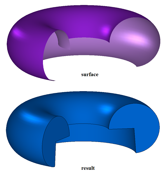
Fig. 13
Fig. 14 shows a cylindrical surface and a body constructed on it:
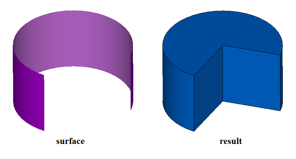
Fig. 14
Fig. 15 shows a conical surface and a body constructed on it:
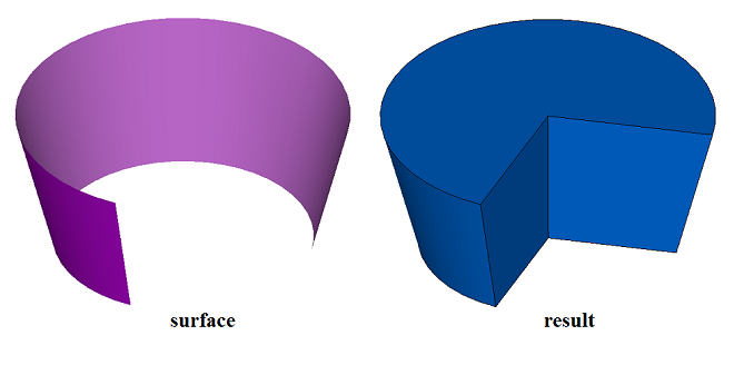
Fig. 15
If the listed surfaces are cyclically closed, the bodies constructed on them will have the corresponding shape. If the surface is not one of the listed elementary surfaces, the function returns the error code rt_Error.
The ElementarySolid() function adds the MbElementarySolid builder to the log of the constructed body (declared in cr_elementary_solid.h).
In the test.exe test application, constructing an elementary body is performed via the «Create→Body→By Points» and «Create→Body→Based on the surface→On an elementary surface» menu commands.