Anton Sidyakin, software engineer, ASCON, presents his experience with C3D Toolkit’s polygonal modeling tools, experiments, and road maps for the future.
Strictly speaking, polygonal objects have already been used to visualize solids. Since sketching and object shaping are not exactly what KOMPAS 3D is made for, we focused on constructing parametric models from sketches either designed in other software or obtained through 3D scanning.
When polygonal modeling was not yet available in KOMPAS-3D, polygonal objects had to be imported as follows.
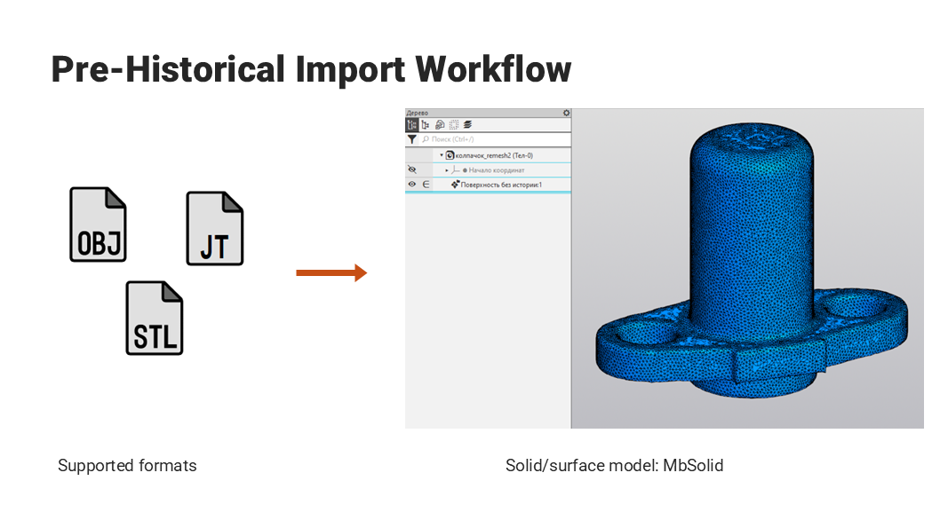
Fig. 1
Polygonal models were automatically converted from any supported format into a solid. For each triangle, the system created flat faces. Their edges and vertices were eventually stitched together to build the resulting solid.
The process was optimized to some extent. For example, adjacent triangles with identical directions of their normals were stitched into a single face. The process is shown in the image. Note the area with a solid fill. A rebuilt solid polygonal body was visualized using a newly generated triangulation mesh.
As a result, the import was slow because it took time to build a solid first.
Further editing of such solids was challenging due to the significant number of features. Adding associative relationships to such solids was equally problematic. Representing the topology of a polygonal object as the topology of a solid body required significant modeling resources and consumed considerable disk space.
To overcome these issues, we decided to add a polygonal object to the design tree. The object is shell defined by the MbMesh class. In this way, we perform conversion into a solid at later stages.
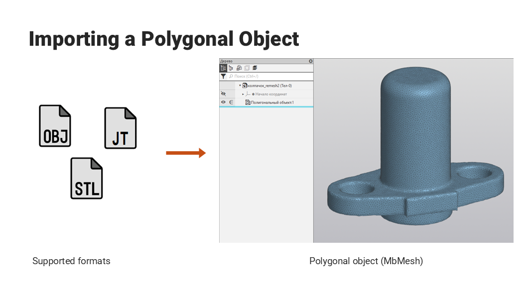
Fig. 2
To visualize the resulting polygonal object, we use the mesh loaded from the source file for display. Now let us check the numbers.
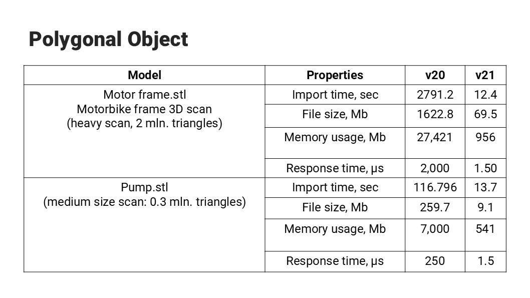
Fig. 3
A comparison of KOMPAS 3D v20 and v21 (the latter supports polygonal objects) performance, using two polygonal objects (a heavy scan of a motorcycle, and a medium-complexity scan) demonstrates significant improvements.
What can we do with this polygonal object? At the very least, we can see it.
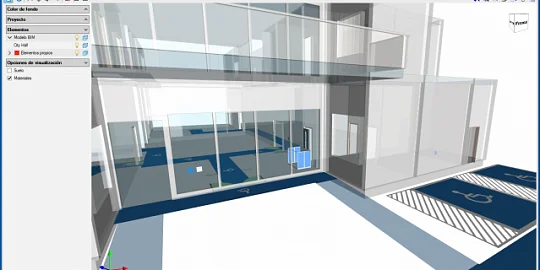
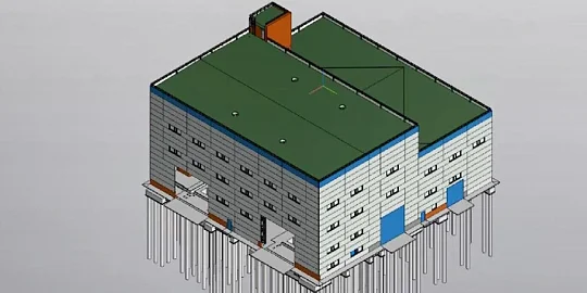
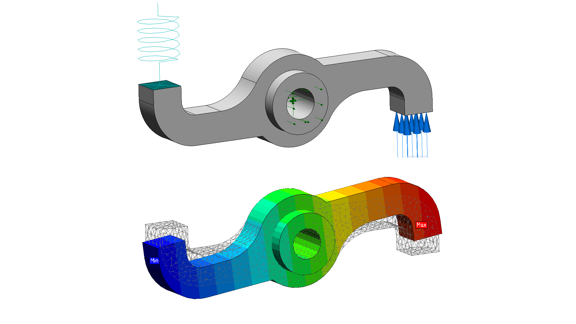
KOMPAS 3D applications need to show polygonal objects to their users. For example, APM FEM visualizes topology optimization results. Since the polygonal object is lightweight, it can be used as a scene environment, or even represent a heavy assembly. Meanwhile, we wanted to add reverse engineering functionality to KOMPAS 3D, that is, converting a polygonal object into a parametric solid model.
What tools do we have to do this?
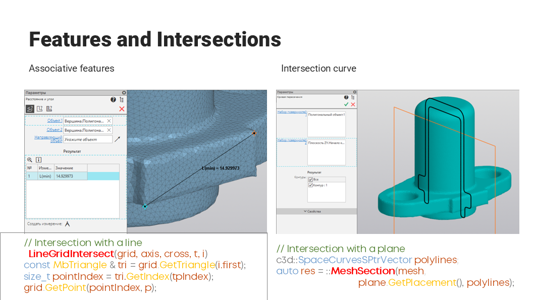
Fig. 4
Making associative relationships with the entities of a polygonal object is usually straightforward. Find an entity containing the look-at point, and save the index of the triangle for subsequent use. The left image shows how the associative relationship with the vertices of a polygonal object is used for measurements.
You can also use the MeshSection function to draw sections of polygonal objects. It generates an array of polylines. The function can draw a sketch to be used in common solid modeling operations such as rotation or extrusion. With these two tools, you can reverse-engineer some simple models, However, C3D PolyShaper offers other, even more exciting, capabilities to fit analytic surfaces onto triangulated meshes.
To fit an analytic surface, we need to separate the region that would be associated with that analytic surface.
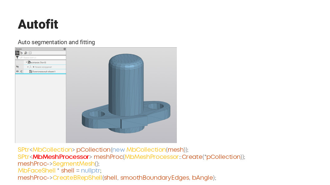
Fig. 5
This process is called segmentation. We were interested in the automated segmentation and analytic surface fitting functionality provided by the MbMeshProcessor class. This image shows a solid produced by the MbMeshProcessor class from a polygonal mesh with virtually no user input. This works with CAD meshes as well. However, internal testing showed that this approach is not as efficient with 3D scans. So we decided to move to add more control over segmentation and fitting. It was possible for sure.
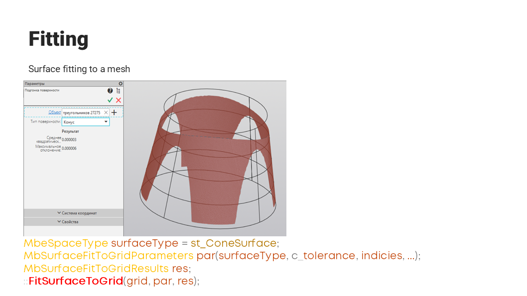
Fig. 6
The FitSurfaceToGrid function analyzes the surface type and some parameters and “best fits” the analytical surface to the selected triangles of the polygonal mesh. The image shows that in this case, the best fit surface is a cone.
We ran a comparative test of the fitting functionality in KOMPAS 3D and in the software from another which also supported surface fitting.
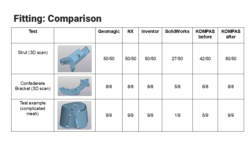
Fig. 7
The testing discovered that the other vendor’s software had some performance issues and a not-so-friendly user interface. It was also found that our product had issues fitting meshes into noisy or defective polygonal objects. The C3D Labs team promptly made improvements. As you can see in the last column, KOMPAS 3D performance matches that of the other vendor’s products.
Since we had given up on automated segmentation, we had to think about a manual solution. That’s how we invented the Brush tool.
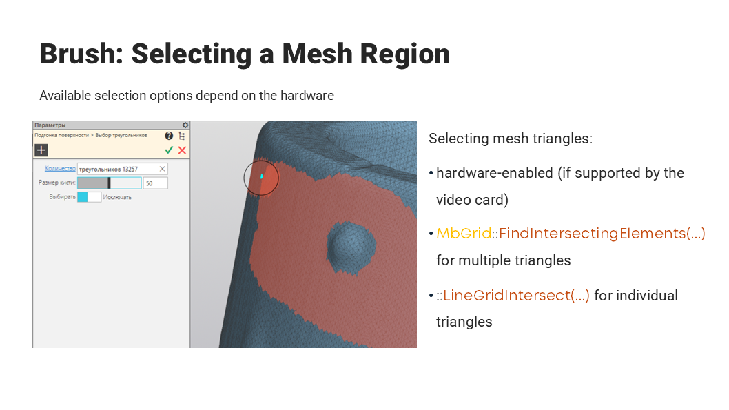
Fig. 8
With it, the user selects specific mesh triangles to be passed to the FitSurfaceToGrid function for fitting. This is especially convenient for selecting single triangles using the LineGridIntersect function. Use the FindIntersectingElements function to select triangles inside the pipe. With a proper video card, it can be hardware-implemented with an extra video buffer for rendering.
The FitSurfaceToGrid function also supports constraints.
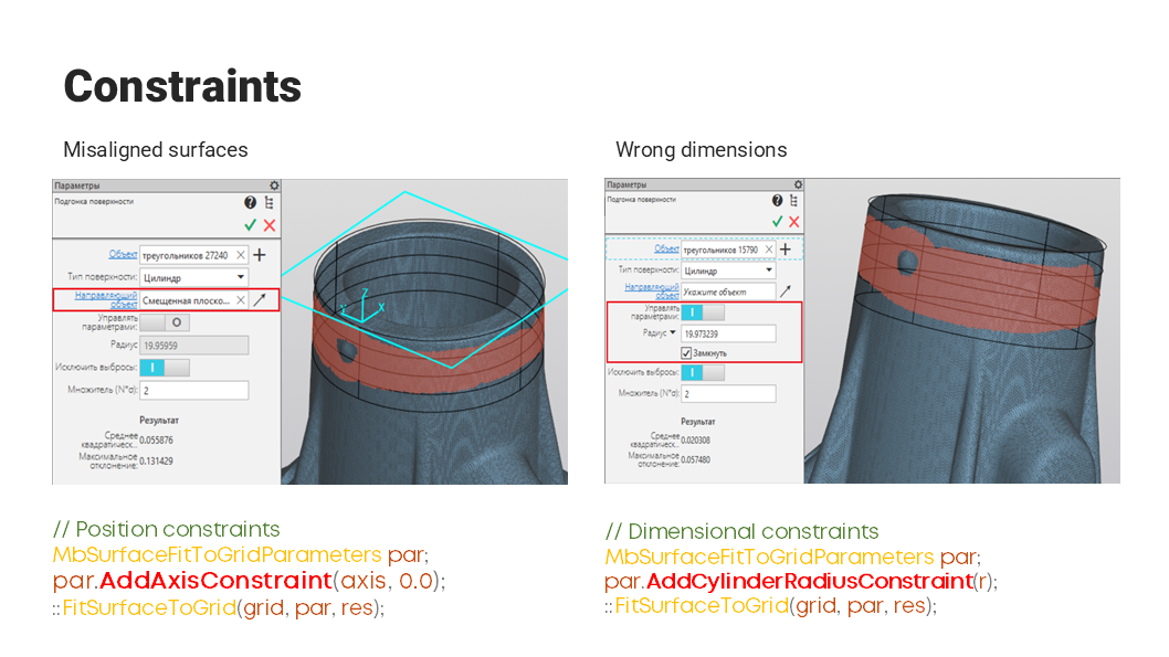
Fig. 9
For example, consider the left image. The fitted cylindrical surface has to be perpendicular to its end face. To do this, call the AddAxisConstraint with the axis as an argument. Then the fitted surface will be perpendicular to this axis. More constraints are also applied to the cylindrical surface. If the radius value is not exact, as in this case, you can manually set it by calling the AddCylinderRadiusConstraint function. It will result in fitting an analytic surface with the given radius.
So, how do we assess the reverse engineering results and the model quality? There is a way.
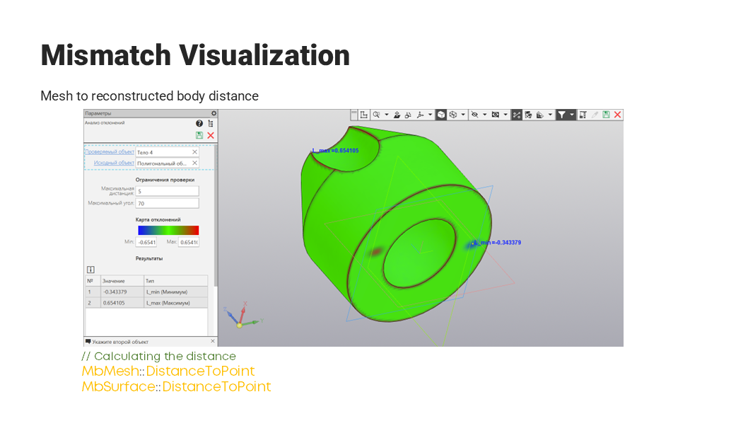
Fig. 10
First, we need to align the body with the polygonal object, and then calculate the distance between them. There are suitable functions in the MbMesh, Surface, and MbSolid classes. If we plot these distances as a heat map, green would represent good quality, i.e., the minimum distance, while blue and red regions on different sides of the original surface indicate deviations.
At the moment these are all polygonal modeling capabilities available in KOMPAS 3D. As the polygonal API C3D is expanding, KOMPAS-3D will have more polygonal functions.
For instance, we are going to introduce fitted surface auto-detection, combined solids and polygonal objects, a new topological object, and curvature-based automated segmentation tools. Concurrently we are developing mesh diagnostics and healing capabilities. Work is in progress for the first two areas.
FitSurfaceToGrid could automatically detect the type of surface to be fitted before, but our tests showed its poor performance.
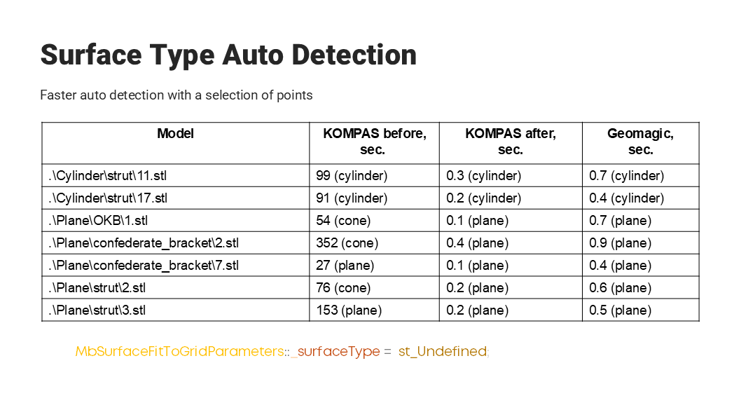
Fig. 11
The C3D Labs team made some improvements to use not the entire surface, but some representative set of its points for auto-detection. Now, the auto-detection is fast, even compared to competitor products.
Another aspect is the object alignment overlap to estimate the quality of reverse engineering.
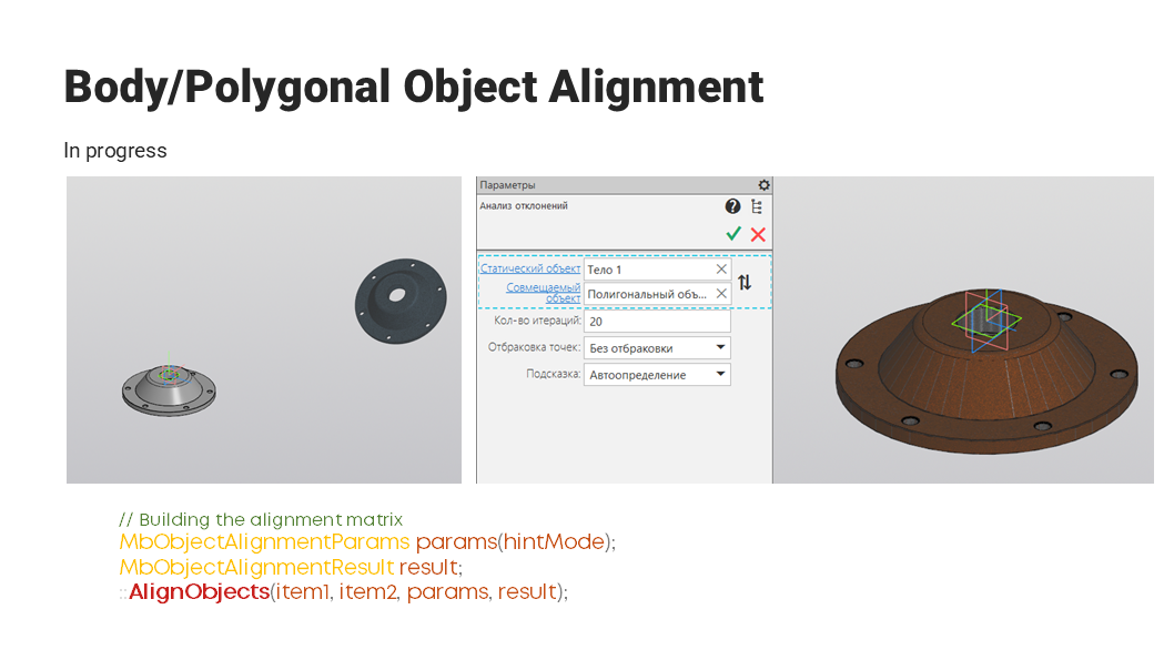
Fig. 12
For this purpose, we have the AlignObjects function. It returns the transformation matrix for one of the objects from the parameters or manual user input. This tool is under development; the final version may differ.

Anton Sidyakin
Software Engineer
ASCON