C3D PolyShaper

Edit, check, and patch polygonal geometry
Evaluate

The polygonal representation uses vertices, edges, and flat facets to build faceted 3D bodies. C3D PolyShaper is a toolbox designed to diagnose and patch polygonal objects.

Diagnostics and Patching

Polygonal meshes may have geometric and topological issues. The list of geometric model errors can be extensive, including such issues as gaps and openings, duplicated vertices, degenerate triangles, and non-manifold geometry. and so on. Such errors can cause most algorithms to fail. Diagnostics and patching are essential stages in polygonal modeling.

C3D PolyShaper offers:

  • mesh diagnostics
  • fixing degenerated triangles
  • mesh stitching
  • fixing inconsistent normals
  • checking for non-manifold geometry
Diagnostics and Patching

Simplification, Refinement, and Remeshing of the Triangulation Mesh

Reducing the number of triangles improves the performance. C3D PolyShaper has two mesh simplification options: to a given number of triangles or a given accuracy. One can obtain a set of simplified meshes with different levels of detail. The simplification algorithm guarantees the preservation of the topological properties of the polygonal object.

The reverse local mesh refinement tool is used for computer-aided analysis to enhance the local simulation accuracy. It preserves a smooth transition from larger to smaller triangles.

Remeshing improves the mesh quality by making the triangles as equilateral as possible. Better mesh contributes to the reliability of many algorithms and simulation processes.

Simplification, Refinement, and Remeshing of the Triangulation Mesh

Editing

C3D PolyShaper offers the following polygonal mesh editing tools:

  • deleting triangles
  • Boolean operations
  • plane sections
  • mesh trimming by a cube of a specified size.
Editing

Polygonal Model Diagnostics

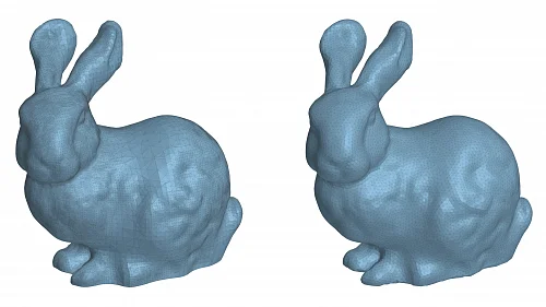
C3D PolyShaper can validate meshes generated by 3D scanning, topology optimization, and other methods.

When it is known in advance that objects should match (for example, when comparing a CAD model to a 3D scanned model), we can apply automatic or semi-automatic object matching for subsequent comparison.

Another approach is reverse engineering when a polygonal model is converted into a solid. For this, analytic surfaces are approximated with the least squares method. The surface type is either auto-detected or selected by the user, such as plane, cylinder, cone, sphere, or torus. The mesh sensitivity to noise can be adjusted to meet various criteria. The shape control tool aims to prevent the creation of surfaces that are close to degenerate, such as nearly flat or nearly cylindrical cones. The inputs are a set of triangles and the desired accuracy.

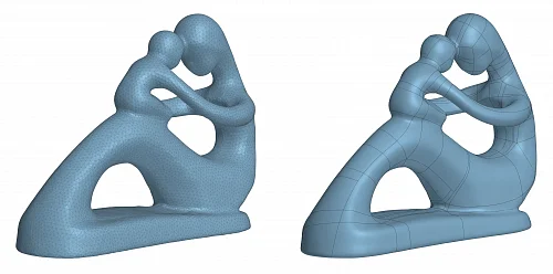
Another area involves the automatic conversion of mostly free-form models into a shell composed of NURBS patches.

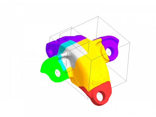
As a rule, what we require is not just the mesh itself, but rather the mesh with its facets logically divided into some groups. The segmentation builds the topology of the polygonal model similar to conventional B-Rep models. The difference is that the faces consist of connected groups of facets, while the edges are composed of sequences of mesh edges. Each topology segment may have an attribute. The attribute can be a number, vector, surface, or arbitrary data structure.

Polygonal Model Diagnostics

Other C3D Toolkit Modules

Up