In June, a new release of Renga was introduced with a remarkable variety of axonometric projections — no other comparable software offers such a wide selection. In addition, the accompanying update to Renga Architecture featured significant enhancements to the Doors tool, and the update to Renga MEP adds heating systems.
Renga is a family of BIM software programs for architectural, structural, and MEP (mechanical, engineering, plumbing) design that is being developed using our C3D Toolkit. To learn how the C3D Modeler geometry kernel and the C3D Solver parametric kernel were used to create new functions in Renga, we spoke with Renga Software developers Yevgeny Korostelev and Andrey Bolshakov, and CTO Ilya Maz.
Axonometric Projections
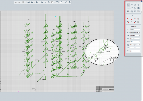
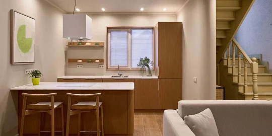
The new Axonometric View tool offers 44 kinds of projections and is available with all programs in the Renga series. The projections are defined by the RF State Standard, "ESKD Axonometric Projections." Axonometric projections are vital for Renga MEP users designing interior systems, such as water supplies and sewer systems (see figure 1), and are a mandatory part of design documentation specified by the RF State GOST SPDS standard.
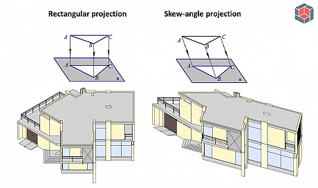
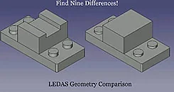
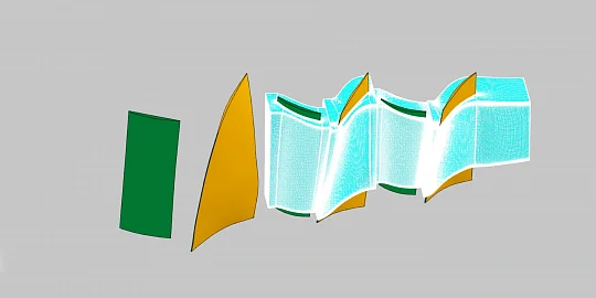
Renga has always offered standard projections for floor plans, facades, section views, and the like. But this release adds rectangle and skew-angle projections (see figure 2). C3D Modeler already provided a ready-to-use method for rectangular projections, but a new algorithm needed to be developed for the skew-angle projection.Renga Software and C3D Labs joined efforts to solve skew-angle projection by starting with a rectangular projection and then transforming it to a flat projection. Objects are projected onto the auxiliary plane in an orthogonal manner using the GetVestiges method of the C3D Modeler kernel. Then, transformations involving scaling and rotation are performed using an operation applied to the C3D Modeler’s primitives. The result of the transformation is the desired skew-angle projection on the plane.
Yevgeny Korostelev (Renga Software):
“We can display model projections on a drawing, obtain them in a vector view, and then save them in various vector formats. Renga MEP requires axonometric skew-angle frontal isometrics, and so we implemented a construction algorithm using the C3D Modeler geometric kernel.
I should add that most other BIM systems do not support skew-angle projections, thus reducing user options. In my opinion, this restriction should be eliminated, and we are glad to present new options for drawing layouts that are based on modern standards.”
New Doors Tool in Renga Architecture
Like all BIM systems, Renga Architecture is based on object design principles, in which a 3D model of a building is created using a range of objects, such as walls, doors, columns, stairs, and so on. The parameters of the objects are set through the style of the related tools.
Renga Architecture’s June release enhances the Doors tool so that you can now use styles to configure parameters of the door’s frame, doorstep, door lining, door panel, and casement (see figure 3). The C3D Modeler geometry kernel is responsible for creating the door’s 3D model using the parameters that you specify.
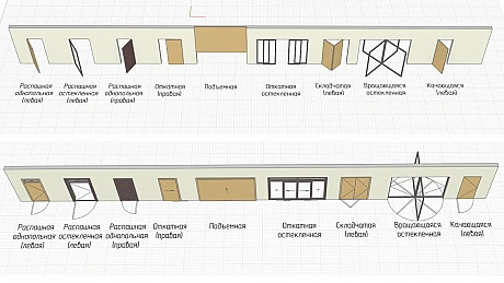
{Figure 3} Comparison of Renga Architecture displaying 3D doors in the prior version (upper figure) and in the new version of (lower figure)
To display door opening lines in drawings, Renga developers used the C3D Modeler function that shades curves by solid bodies during projection. This was, by the way, a function implemented in our kernel last year at the request of Renga Software.
New Heating and Water Supply in Renga MEP
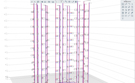
The object-based approach is also used by Renga MEP: a route is now the main object when designing water supplies and heating systems (see figure 4). Routes are contours made of straight-line segments and connect water sources to equipment and plumbing fixtures. Routes attach pipes, latches, accessories, parts, and fittings.
As Renga is designed to maximize the automation of designers' work, users do not create the route manually. Instead, they select two objects, and then the system creates the route between them using specific algorithms.
When a plumbing fixture needs to be moved but the route’s connection points must remain the same, Renga’s unique editing algorithm finds the route segments closest to the object (or to the parent route being edited) that define the maximum number of degrees of freedom, and then changes their length.
To implement the algorithm, the developers at Renga Software used the 3D solver from the C3D Solver parametric kernel and its Linear Pattern constraint to arrange objects along a defined line. The constraint system does not include attached elements (pipes, parts, accessories), as they should not affect the system’s solution.
Andrey Bolshakov (Renga Software):
“To edit a route, we call up a 3D Solver function, transfer a reference object to it (i.e., the start of the route segment), and then add the line on which the segment is located. The end point is added using another function from 3D Solver. We add a distance between the start and end points, and then apply the scaleType option to change the segment’s length:
auto pattern = GCM_AddLinearPattern(m_system, startPoint, dirLine);
GCM_AddGeomToPattern(m_system, pattern, endPoint, distance, GCM_NO_ALIGNMENT, scaleType);
We set the GCM_LINEAR_SCALE scaleType for those segments that define the degrees of freedom. For other elements whose length should not be changed, we use the GCM_RIGID scaleType.
"We also fix the direction of segments. If segments are no longer parallel to the original, the angle between them may change, but we work with a limited set of fittings, specifically branch models and T-branches. It is inconvenient to search for new branch models that fit new angles after modifying the route, and so we simply fix the line that defines the linear pattern:
GCM_FixGeom(m_system, dirLine);
“In addition to simple routes that connect two items, there may be branches — one end of a child route may be connected to a parent route, rather than to a piece of equipment. So we added another requirement: the connecting point of the child and parent routes (a T-branch) may not leave the segment’s limits.
“We need a ‘Point on Segment’ constraint, but C3D Solver does not yet support it, so we made our own method to implement it. We added the ‘Point on Line’ constraint to GCM_COINCIDENT and GCM_LINEAR_PATTERN. The line is the line of the parent route segment to which the child route goes, and the point is the point of the T-branch.
“In solving the system of constraints, we check if the new T-branch’s point is located within the segment. If the point is outside the segment, we remove the initial constraint using the GCM_RemoveConstraint method, and then apply the Coincident constraint to the T-branch’s point and its closest segment end. The system is then solved again.”
Conclusion
What does the experience of using C3D Toolkit for Renga show us? Although 3D modeling in a BIM system is not more complicated than in MCAD, BIM has certain specific requirements which, fortunately, C3D Modeler and Solver take into account. If some of our components do not support a function, we either add it based on customer requests, or else find our own solution using available methods.
For more information about Renga Software, please visit https://rengabim.com/en/ .

