In this note, we are focusing on two new features in our C3D Solver 2022 constraints module, and demonstrate how to use them with code fragments. The constraint manager includes two- and three-dimensional solvers that allow you to impose a variety of constraints on bodies in both 2D and 3D space.
New in 2D Solver: Equidistant Curves
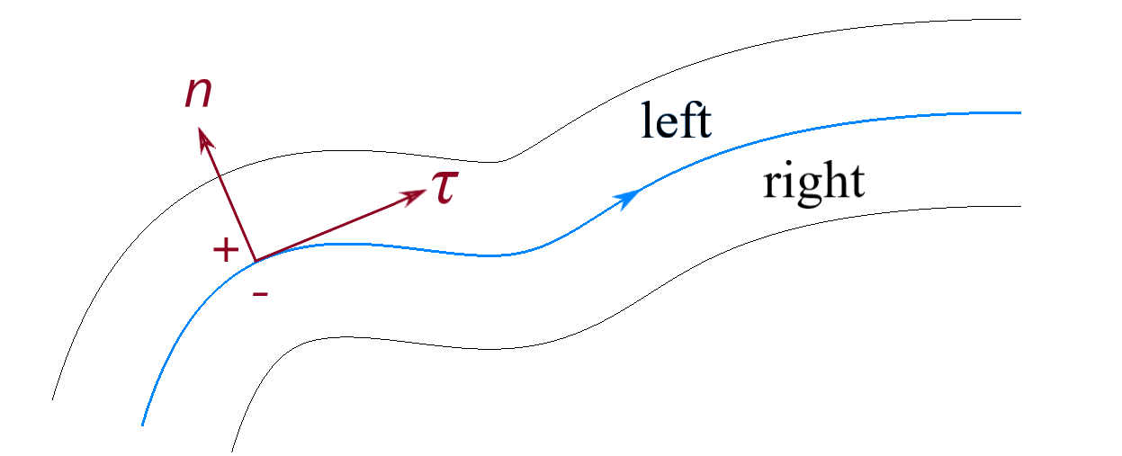
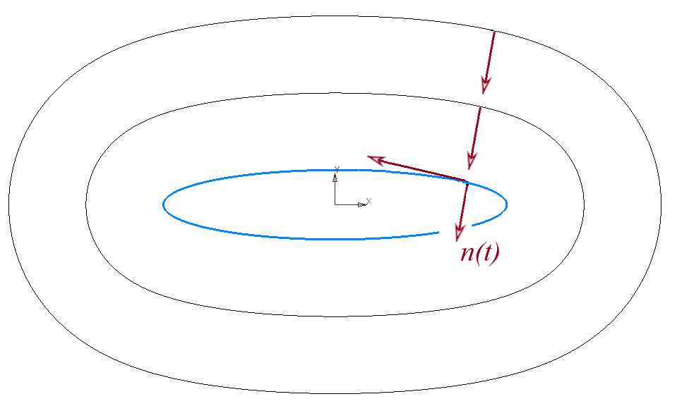
The primary new feature in our 2D constraint manager is offset (equidistant) curves. Offset curves are useful in a variety of areas, such as building equidistant contours for CNC milling machine paths. In our solver, offset curves are represented by a set of points located at a set distance “d” from the base curve.
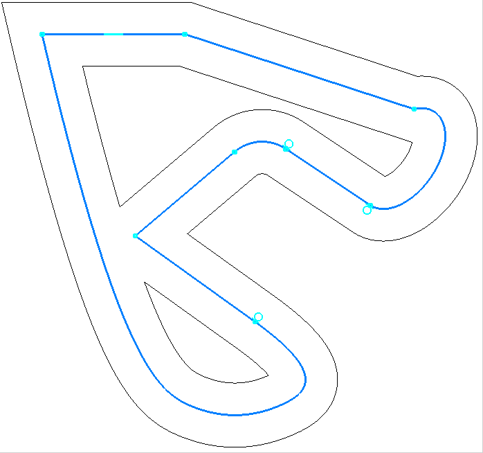
The 2D solver supports the following types of constraints for this new type of curve:
- Fix an equidistant curve
- Incidence of a point and an equidistant curve
- Touch
- Symmetry
- Distance from an equidistant curve to a point, straight line, segment, circle, and another equidistant curve
All constraints for linear objects are also available for offset curves when they are based on linear curves -- parallel, perpendicular, horizontal, vertical, and angular constraints.
We implemented several new C3D Solver API methods for working with the new curves. One of the new methods registers the equidistant with the solver, taking as parameters its base curve and the value of the offset:
// Add an equidistant curve
geom_item GCE_AddOffsetCurve(GCE_system, geom_item curve, double offset);
Another new function allows you to fix the offset of a curve, because by default its value can change:
// Fix an offset of equidistant curve
geom_item GCE_FixOffset(GCE_system, geom_item curve);
With another new method, you can equate the offsets of two different equidistants:
// Equate offsets of two equidistant curves
geom_item GCE_AddEqualOffset(GCE_system, geom_item curve1, geom_item curve2);
The code fragment below (in C++) demonstrates how to create and add equidistant curves for a linear segment and its points:
// Create a constraint system
auto solver = GCE_CreateSystem();

// Declare point GCE_point p_
GCE_point p_;
p_.x = 1.; p_.y = 0.;
auto p1 = GCE_AddPoint(solver, p_);
p_.x = 3.; p_.y = 0.;
auto p2 = GCE_AddPoint(solver, p_);
geom_item pnts[] = { p1, p2 };

// Add linear segment by two points
auto lseg = GCE_AddLineSeg(solver, pnts);
// Create the 1st offset line of the segment
auto offsetLSeg1 = GCE_AddOffsetCurve(solver, lseg, 5.);
// Create the 2nd offset line of the segment
auto offsetLSeg2 = GCE_AddOffsetCurve(solver, lseg, -4.);
// Create the 1st offset circle of the point p1
auto offsetPoint1 = GCE_AddOffsetCurve(solver, GCE_PointOf(solver, lseg, GCE_FIRST_END), 4.5);
// Create the 2nd offset circle of the point p2
auto offsetPoint2 = GCE_AddOffsetCurve(solver, GCE_PointOf(solver, lseg, GCE_SECOND_END), 5.5);

// Equate offset curves
GCE_AddEqualOffset(solver, offsetLSeg1, offsetPoint2);
GCE_AddEqualOffset(solver, offsetPoint2, offsetLSeg2);
GCE_AddEqualOffset(solver, offsetLSeg2, offsetPoint1);
// Fix the offset of the 1st offset line of the segment
GCE_FixOffset(solver, offsetLSeg1);
// Evaluate the system
GCE_Evaluate(solver);
GCE_GetCoordValue(solver, offsetLSeg1, GCE_OFFSET);

// Remove the system
GCE_RemoveSystem(solver);
3D Solver: Interval dimensions
Previously, we provided a C# interface for only the 2D solver; we now supply it for the 3D solver as well.
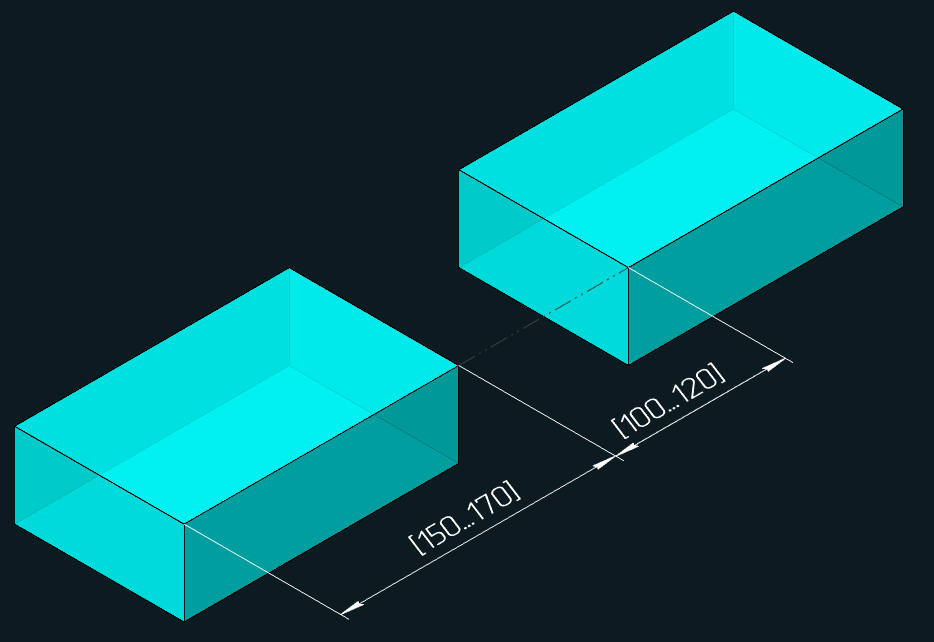
Among the new methods of the 3D solver, one is a distance interval function (the Range constraint). This constraint represents a dimension in which the value varies at specific interval. It can be imposed between two bodies, or between two parts of the same body.
An important feature of the interval constraint is that the range of acceptable values coincides with the driving dimensions. This lets you switch smoothly between intervals and related driving dimensions. In addition, intervals can be imposed between all types of objects for which similar driving dimensions are applicable.
You can use the new function through the extended solver API. The pre-existing function GCM_constraint GCM_AddDistance(...) adds a driving dimension; its fourth parameter was changed:
// Set linear increment dimension
GCM_constraint GCM_AddDistance(GCM_system, GCM_geom g1, GCM_geom g2, const GCM_interval &, GCM_alignment);
The above code fragment demonstrates the addition of an interval dimension to a new function, where the fourth parameter GCM_interval represents a structure that stores the values of the interval boundaries.
// The interval of acceptable values for an increment dimension
struct GCM_interval {double lBnd, rBnd;};
The code fragment (C++) below demonstrates how to create and add an interval dimension between two bodies:
// Create a constraint system
auto solver = GCM_CreateSystem();

// Add body 1 to the system
auto box1 = GCM_AddGeom(solver, GCM_SolidLCS(MbCartPoint3D::origin, MbVector3D::zAxis, MbVector3D::xAxis));
auto box1XY = GCM_SubGeom(solver, box1, GCM_Plane(MbCartPoint3D::origin, MbVector3D::zAxis));

// Add body 2 to the system
auto box2 = GCM_AddGeom(solver, GCM_SolidLCS(MbCartPoint3D::origin, MbVector3D::zAxis, MbVector3D::xAxis));
auto box2XY = GCM_SubGeom(solver, box2, GCM_Plane(MbCartPoint3D::origin, MbVector3D::zAxis));

// Initialize an interval structure with boundary values
GCM_interval interval{ 1.5, 7.5 };
// Add a dimension
auto itrvlDist = GCM_AddDistance(solver, box1XY, box2XY, interval);
// Evaluate the system
auto result = GCM_Evaluate(solver);

// Remove the system
GCM_RemoveSystem(solver);
Future Enhancements
In the future, we plan to add an interval constraint for angular dimensions. After that, we plan to add both groups of interval constraints to the 2D solver.