Introduction
This article is an answer to the question raised by one of our customers during the C3Days conference on how to jointly use 2D and 3D solvers in an application and when such a combination may be appropriate.
To answer this question, let us consider using 2D and 3D solvers together illustrated by creating a simplified parametric model of a standard high-rise building. The example is purely fictional and has nothing to do with designing a real building, but it illustrates one of the methods for arranging interaction between 2D and 3D solvers within a client application.
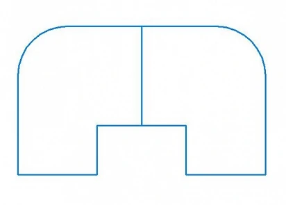
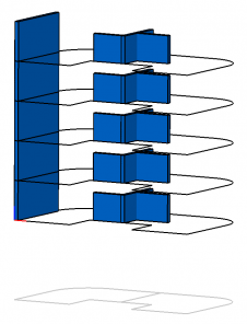
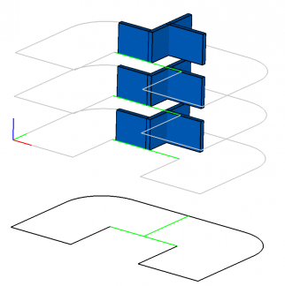
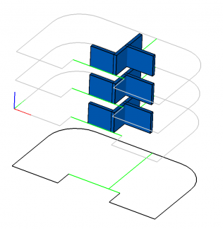
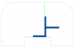
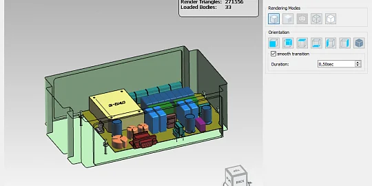
Let us suppose that we have a 2D sketch (Fig. 0.a) that sets an apartment plan for a floor. Using this sketch, we will create a fully parameterized 3D building (Fig. 0.b) and demonstrate how to manipulate any of its parts without disturbing the 3D constraints applied to its structural elements.
Elements
Firstly, let's prepare "bricks" that we will use to create our building. Typically, in a client application for working with geometric objects (curves, surfaces, bodies, etc.) when solving problems generated by the domain-specific area of an application (e.g. for visualization), its own internal representation of geometric objects that is the most suitable for its domain-specific area is used. We will call such an internal representation of geometric objects a client representation or a model representation. To use the geometric constraint solver, we need to map client geometric objects to the domain-specific area of the geometric constraint solver. We will call such representation a parametric representation of geometric objects.
To create a 2D sketch, we will use the 2D MbCurve curves of the C3D Modeler. For our task, we will use circular arcs and line segments. To create a parametric representation of a curve, we need to register it in the C3D Solver using the respective solver API calls. To aggregate these two representations of the same curve, let's create a Curve2D class. It is important to note that the client and the parametric representations of the curve are independent of each other therefore we need to synchronize them. For this purpose, we will use the Update method: after modifying the sketch, we will request new curve positions from the 2D solver and update their client representation. An example of the implementation of the Update method for updating the state of a client line segment is given in Fig. 2
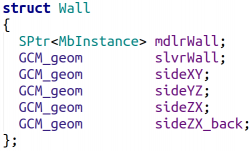
We define the basic three-dimensional object of our model in a similar way. Let it be a simple rectangular block (or a parallelepiped, in the language of mathematics). For the client representation of the block, we will use a standard solid body (MbSolid) of the C3D Modeler placed in the MbInstance insertion, so that we can control the position of the block in space through the local coordinate system (LCS) of the insertion (MbPlacement3D). Since we are going to apply constraints not only to the whole block, but also to some of its faces, let's register some of the block faces in the solver as planes and indicate that these planes are not independent of each other but are parts of a more common parent object. 3D solver has a special function for this purpose — GCM_SubGeom. In other words, we register the plane in the 3D solver as a sub-object of some parent block (parallelepiped) and, therefore, rigidly fixing it within the coordinate system of this block. It means that it can freely move in space, but in such a way that its position remains constant within the coordinate system of its parent block. Let's create a Wall class to aggregate the client representation of the block and its parametric representation in the 3D solver that also includes the block's faces (Fig. 3).
It is very simple to synchronize the block (Fig. 4): we need to request an updated position of the LCS of the parent object in the global coordinate system (GCS) from the 3D solver and assign this new position in space to the MbInstance insertion which is responsible for the client representation of the block. Since auxiliary faces were defined as sub-objects of the block their positions do not need to be controlled: the updated LCS of the block defines the exact locations of its faces in space.
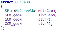
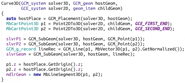
So, we have defined simple bricks to construct "pure" 2D and 3D elements of our model. Now we define a brick that will be the connecting link between 2D and 3D objects that are completely independent of each other and controlled by the 2D and 3D solvers, respectively. As such a connecting link, we will use 3D curves that will be the mapping of 2D curves controlled by a 2D solver into 3D space. These 3D curves will always belong to 3D plane to which they are mapped. To work with such curves on the client application side, we will use the MbCurve3D curves of the C3D Modeler. On the 3D solver side we will use unbounded 3D curves (in our example, circles and lines) and the two points that define the bounds of theses curves (Fig. 5). The class that aggregates these curve representations we will call Curve3D.
Fig. 6 shows a possible implementation of a constructor that maps a 2D line segment into a 3D one. The constructor's input data is the floor’s LCS (hostGeom), whose Oxy plane contains the mapped 3D curve, the original 2D curve (childGeom), as well as 3D and 2D constraint systems that control the plane and the curve, respectively. By requesting the line segment coordinates from the 2D solver, we register it in 3D solver as a sub-object of the parent plane.
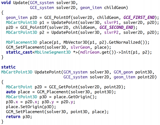
An important distinction between this “brick” of our model and the previous ones is its synchronization between client and parametric representations. Since the 3D curve is controlled by its 2D counterpart, first of all, we need to update the coordinates of the 2D curve that will be the new position of the 3D curve in the LCS of its parent plane. Then, we have to calculate new position of the 3D curve in space and assign this position to it representation in the 3D solver. Then, we need to update the client representation of the 3D curve (mdlrGeom). An example code for updating the client representation of a line segment is shown in Fig.6.a
Now, we have three basic bricks to construct our building: 2D curves (Curve2D), 3D wall block (Wall) and 3D curves (Curve3D). It should be noted that 2D curves are controlled by the 2D solver and 3D bodies are controlled by the 3D solver, while 3D curves are controlled by both solvers at the same time: the 2D solver controls curves positions within the LCS of parent planes, while 3D solver controls their orientation in space through the parent plane position.
Now, we can start constructing the building using the bricks described above. Let's start with the first floor.
Creating a floor plan
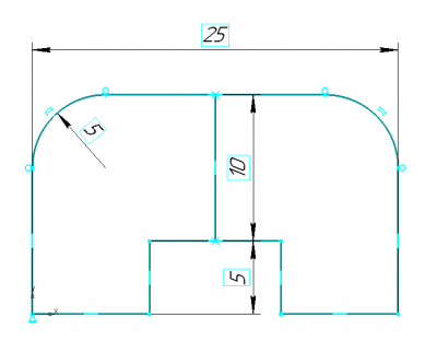
To construct our high-rise building, we need a standard template of the apartments plan on the floor. As the basis, let us use a two-apartment floor plan shown in Fig. 7.
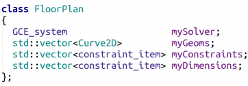
To create such a sketch, let's create the FloorPlan class that will aggregate a 2D constraint system (mySolver), 2D curves (myGeoms), logical (myConstraints), and dimensional (myDimensions) constraints imposed on the curves. We will use the dimensional constraints as controls for the floor plan.
To display the sketch in the editor, we need one more data field (myPlace) — the position of the sketch in 3D space. We create the floor plan template controlled by the constraint system in the constructor (Fig. 9). Details of the creation of curves and the imposition of constraints on them defining the sketch in Fig. 7 are hidden in the _FormulateSketchTemplate function since they are not important for our task but occupy many lines of code. Note that since the floor plan creates a constraint system in the constructor and owns it, we must remove it in the destructor to avoid memory leaks.
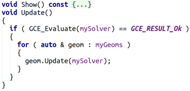
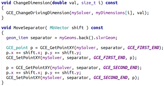
The interface of the class we need to work with our sketch will consist of four methods. Firstly, it is the Show function that is responsible for displaying the floor plan on the screen (its implementation is not of interest for the problem we are considering and therefore will be omitted). Secondly, it is the Update function: after manipulating the sketch, we need to solve the constraint system and, if it is solved successfully, update the position of all displayed curves accordingly with their new position in the solver (Fig. 10). Thirdly, there are two functions for manipulating the separator between two apartments in our template floor plan: ChangeDimension — to modify the separator size and MoveSeparator — to move the separator. The implementation of these two functions is elementary and consists in a simple redirection to the corresponding solver API calls (Fig. 10).
Creating a floor
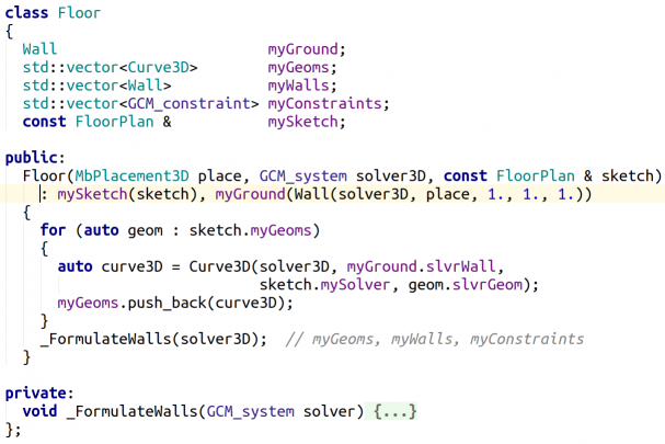
Let us now create the 3D model of the building. For this purpose, we will create an auxiliary class Floor that will responsible for handling each separate floor of our building.It will consist of the floor zero level (myGround), 3D walls (myWalls) to be attached on the floor and 3D curves (myGeoms) that are mapped from the 2D floor plan (mySketch) to the floor plane (myGround). Constraints that bound 3D elements of our construction will be stored in the myConstraints data field. To create an object of the Floor class, we need the floor position in space, a 3D constraint system that will be used to apply constraints to floor structural elements, and the 2D floor plan (see Fig. 11). In the constructor, we create all the necessary walls. In addition, by running in the loop over all the 2D curves of the floor plan, we create their 3D mappings on the floor plane (Fig. 12; black color is used to draw the 2D floor plan, while gray color is used to draw its 3D mapping on the floor plane) and add them to the 3D constraint system. Using the 3D solver, we can fasten walls to these curves. We will call such walls structural walls. And we will call a 3D mapping of a 2D floor plan a 3D floor plan or a 3D floor sketch.
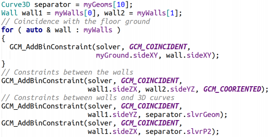
Details of creating walls and binding them with constraints are hidden in the _FormulateWalls function, since they are not related to the subject of this article. We just note that all constraints applied to the floor structural elements can be categorized into three types. Firstly, this is the fastening of walls to the floor (myGround) by applying the "Coincidence of Planes" constraint between the floor (myGround) and the wall face which should be attached to the floor. Secondly, these are the constraints between the walls that will set, for example, the layout of rooms inside an apartment. Each floor may have its individual layout. Thirdly, these are the constraints that fasten structural walls to 3D curves that define the floor plan (sketch). Examples of setting all these three types of constraints are shown in Fig. 13
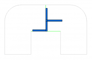
As a result, we have got a floor sample as shown in Fig. 14 (for simplicity, we will not overload our model with a large number of construction elements and therefore will display only the minimum required set of them). All blue walls and the 3D plan (gray and light-green curves) in this figure are placed on the floor plane (myGround). All walls are bound by "Coincidence of Planes" constraints, and one wall (structural wall) is rigidly attached to the 3D curve (separator between our "apartments") of the 3D plan.
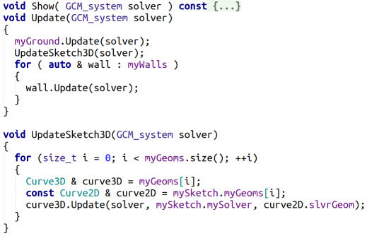
The Floor class, as the FloorPlan class, has the Show method for floor visualization and the Update method for updating all the floor construction elements (walls and 3D curves) according to their state in 3D and 2D solvers (Fig. 15). Updating the 3D floor plan is implemented in a separate function UpdateSketch3D and later we will explain why.
Creating a building
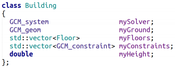
Once we have defined the Floor class, we can start creating a fully parameterized high-rise building. For this purpose, let's create the Building class (Fig. 16). Like the FloorPlan 2D sketch, which owned the 2D constraint system, the Building class will own the 3D constraint system (mySolver). It will have a zero level (myGround) and consist of an array of floors (myFloors) which will have the same height (myHeight) for simplicity. Constraints between the floors will be stored in the myConstraints data field.
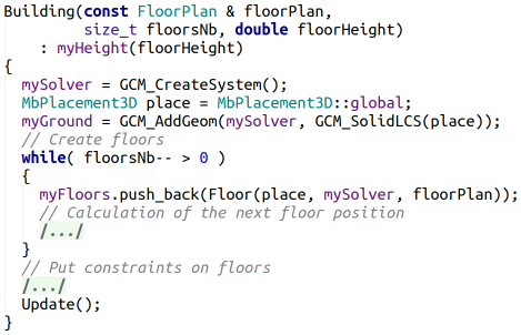
In the constructor of the Building class, we will provide the opportunity to set the number of floors in the building, the height of the floors and 2D plan of the floors (Fig. 17).
In the constructor’s implementation, pay special attention to the part that responsible for binding all floors of the building into a linear pattern of components (GCM_LINEAR_PATTERN) which controls the coordinated position of all floors during manipulations with them: all of them will be placed along the Oz axis of the building zero-level (myGround), while the floors zero-level planes will be parallel and their Ox and Oy axes will be aligned along the Ox and Oy axes of the ground floor LCS.
Since the Building class owns the 3D constraint system, we need to remove it in the destructor to avoid memory leaks (Fig. 19).
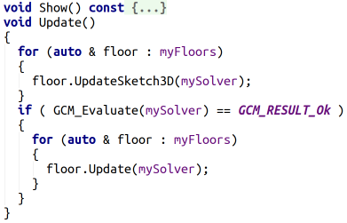
As well as FloorPlan and Floor classes, the Building class will have Show and Update methods (Fig. 20). An important aspect of implementing the Update method is that the curves that form 3D floor plan must be updated twice. Since 3D curves in our example are also controlled by the 2D solver we must request from the 2D solver their actual positions in the LCS of the planes where these curves are the sub-objects before solving the 3D constraint system and transfer these positions to the 3D solver. This will be the first update of 3D curves. Then, we will solve the 3D constraint system and update the positions of all floors and their structural elements. When updating a floor, the curves that form the 3D floor plan will be updated again reflecting the work result of the 3D solver.
To demonstrate how parametrization between the building floors works let us add the ChangeFloorHeight method that will allow to change the floor height (Fig. 21). When we bound all the building floors in the constructor into a linear pattern of components with a constant step equal to the floor height, in terms of the C3D Solver we have actually created a set of driving linear dimensions equal to the distance between the ground floor zero-level plane (myGround) and all other floors zero-level planes. Therefore, to change the floor height, we will use a function provided in the 3D solver API for modifying the driving dimension value - GCM_ChangeDrivingDimension.
Handling the building
Once we have described the Building class, let us show how we can use it together with FloorPlan to create the parameterized 3D building and control its view.
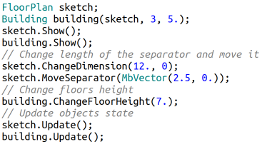
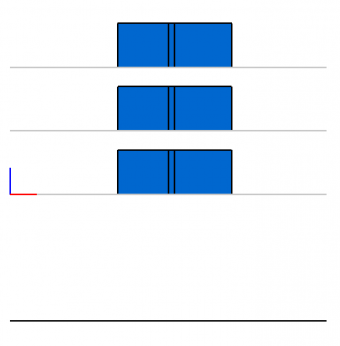
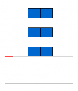
Figure 22 shows an example of a code where the building is created: the three-storey building based on the 2D sketch of apartments layout for floors and floor height equals 5 takes only two lines of code. Figures 23.a, 24.a, and 25.a show the created building in different projections. Figure 22 also shows editing of the 2D apartment layout for floors after creating building: we change the size of the separator between apartments first and then move the separator a little to the right making the left apartment larger than right one. Finally, we change the floor height from 5 to 7. In order to apply the changes, we should update the 2D plan and the building by calling the Update method for the 2D sketch and for the building. The 2D and 3D constraint systems will be solved inside these methods. The result of these modifications is shown in Figures 23.b, 24.b, 25.b. As we can see, 2D and 3D solvers relieve us of the need to take care of 2D and 3D constraints imposed to our model objects. After manipulating the controls, all the 2D and 3D constraints are applied automatically. All that we had to do is to ensure synchronization of the data transfer from the 2D sketch to the 3D solver.
Conclusions
As a result, we have defined a parameterized model of the standard high-rise building that we can edit without taking care of the existing geometrical constraints between its structure elements. This task is performed by the 2D and 3D solvers. The only overhead we have is taking care of data synchronization between the 2D and 3D solvers. As can be seen from the considered example, the combined use of 2D and 3D solvers can give some advantages.
Firstly, by transferring the responsibility for maintaining the constraints between the 3D curves to the 2D solver, we make our system of equations in the 3D solver much more compact, that significantly improves the stability of the process of its solving and, as a result, the overall performance of our program.
Secondly, we have got a well-scalable task. Each 3D floor plan is controlled by the same 2D sketch (i.e. the same system of equations). Therefore, we do not need to create many similar constraints to determine each 3D sketch when creating a new floor. For the same reasons, we do not have to create constraints to bind structure elements of different floors to ensure their coordinated behavior. In the considered example, we used this feature for the coordinated editing of separators between apartments (structural wall) on all floors.
Thirdly, this approach makes it possible to impose constraints to 3D curves that are currently not supported by the 3D solver if they are executed in a plane (e.g. the dimension constraint between two 3D circles lying in the same plane).

Author
Alexander Alakhverdyants
Mathematician and Programmer at C3D Labs

