Many professionals use the 3D modeling function in their CAD systems every day. Not all, however, know what is hidden behind the user interface and its commands to make designing 3D products so convenient. The usability of CAD systems depends on their performance, especially when loading 3D models and working with large assemblies. Engineers rightly believe that responsibility for this lies with the geometric kernel.
CAD users who work with complex 3D models face the same problem: it can take a long time to load large geometric models into their systems. As a result, users may wait for some time before continuing to edit their designs. And then at the start of the work day they are forced to repeat this operation every morning. This seems like a small problem that frustrates users and makes them dissatisfied with their software.
CAD developers do what they can to accelerate their software’s ability to load very large models more quickly. For instance, the popular Russian MCAD system KOMPAS-3D provides users with several different ways to do it: either load the model as a simple rectangular bounding box that represents the model’s extents, load a faceted version that represents the shape of the model, or else load the full model complete with its construction history. Each option loads progressively more data. While this allows users to select faster or more detailed mode, as they prefer, the problem is solved only at the application level.
Another approach is to improve the speed at the file architecture level. JT, for example, is an open format, so it can be used by design systems as well as by 3D model viewers, and even by more complex software that works with metadata. The developers of the JT format made it possible to load two representations of geometry simultaneously -- a simple polygonal model and a detailed boundary representation. So, when users first load a 3D model, the lightweight faceted representation is loaded quickly, which can be used immediately for rendering (viewing the model). Then, if necessary, the heavier boundary representation is loaded, which is necessary for editing the model.
These two examples show that optimizing file loading is in demand at the end-user application level at the lower level one. It is for this reason that C3D Labs has been working at improving the performance its C3D format, native to the C3D Modeler’s geometric kernel. We developed and implemented an extended format for storing the geometric model. This new format reads from the file individual model objects in random (programmer-ese for “arbitrary”) order, and gets information on the model’s structure and its objects without loading the entire model.
Let's look at the new C3D format in greater detail, and see how it differs from the previous format.
How the Traditional C3D Format Worked
In the traditional C3D format, model objects are saved sequentially into one set of File Space clusters (see Figure 2) that has a single write point. If a geometric object refers to another object, then this inner object is written inside the object that references it. When a model object is referenced by several other objects, it is written inside the first object that references it, and is also included in the Registered Objects table. All subsequent objects that reference this object contain an index from the table.

Figure 2. Storing geometric model objects in traditional C3D format
The advantages to this approach are the minimum overhead when writing and reading the model, small file size, simplicity of the software implementation, and high usability of the API. But this approach imposes limitations on the use of the C3D format:
- Information on the structure of the model (or of individual objects) is obtained only after reading the entire model
- It is not possible to load objects in random order, or to import individual objects
These drawbacks occur because the C3D file does not provide information on the storage positions of specific objects. As well, when the object is nested in another object or refers to an object, its storage position is unknown.
And so C3D Labs extended the C3D format to overcome these limitations.
About the Extended C3D format
To update the C3D format, the C3D Labs team first worked out in detail the requirements for the new structure. Some of these requirements had been already formulated, such as the independent storage of objects and the ability to read individual objects – on top of accessing data from the file without needing to read the entire model. Then they determined additional requirements: new interfaces for reading and writing models, for reading individual model objects, and most importantly, maintaining compatibility with the current C3D format.
During the implementation stage, the developers determined where to save the properties and storage locations of objects, as well as the information about the hierarchy. They developed a table of contents mechanism, allowing for the independent storage of geometric model objects, implemented as follows:
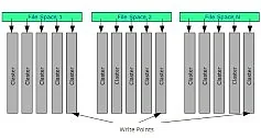
- A specific object contains only those objects that are used exclusively by this object. As part of this approach, the objects belonging to each level of the model are saved in a separate File space, which can be switched between different write points while saving the file (see Figure 3)
- The object’s storage position in the file is used to reference the object
So, what is the final result? Now it is possible to perform single-pass processing of the geometric model while writing the model itself and its table of contents to file. The object tree, or table of contents, includes all objects belonging to the Items type. The object tree is saved to a file in the form of a flat list of nodes, where each node contains the following data for each object:
- Object type
- Object name
- Dimensions of the object and the local coordinate system (if applicable)
- Position in the file to write/read the object in the form of a cluster index and an offset in the cluster
- List of direct descendants of the node
- Object attributes
Application to CAD Systems
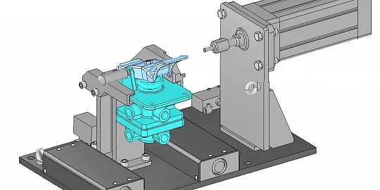
When loading a model from the new extended C3D file format, users can determine which objects should be read and displayed by name, type, size, and attributes (see Figure 4). This function speeds up data loading when users want to read only part of the data from the file, instead of loading the entire model. The newly developed interface for reading data supports both the extended and traditional C3D formats, so compatibility with earlier versions is guaranteed.
The updated structure of the extended C3D format will allow us to further optimize algorithms for writing and reading data, by taking into account the benefit provided by multi-core architectures. This function is currently under development.
You can download the free C3D Viewer application for viewing and converting 3D models, as well as evaluate the C3D Toolkit for CAD, CAM, and CAE software development.


The C3D geometric kernel has been under commercial development by C3D Labs since 2012. In this article, C3D Labs head of programming Tatiana Mitina describes the development of the extended C3D file format.