The quality of a kernel is what makes software useful to users. The primary value of a computer-aided engineering (CAE) system is concentrated in the abilities of its computational kernel. It ensures calculations are accurate, speedy, and reliable.
Before a kernel can do its work, it is necessary to import a model from a computer-aided design (CAD) system into the CAE software, and then prepare it for analysis. These pre-processor operations are performed by a data converter and the geometric modeling kernel, respectively. CAE systems, in particular those using finite element analyses (FEA), impose specific requirements on geometric kernels that in regular CAD systems are not as critical.
Vladimir Podnos is the director of marketing and support at Tera Analysis Ltd., a Denmark-based developer of FEA software for low-frequency electromagnetic, heat transfer, and stress analyses. He explains the requirements for 3D modeling in FEA simulation software:
We’ve enhanced modules in our C3D Toolkit to provide CAE software developers the tools they need to prepare geometric models for analysis.
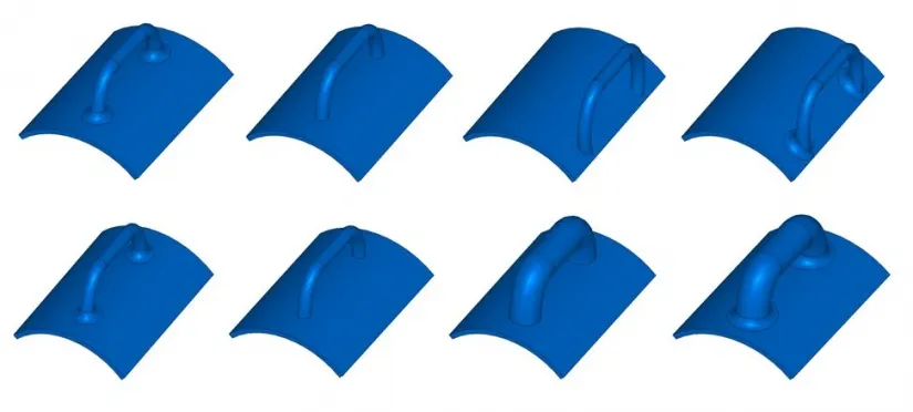
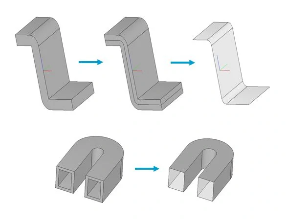
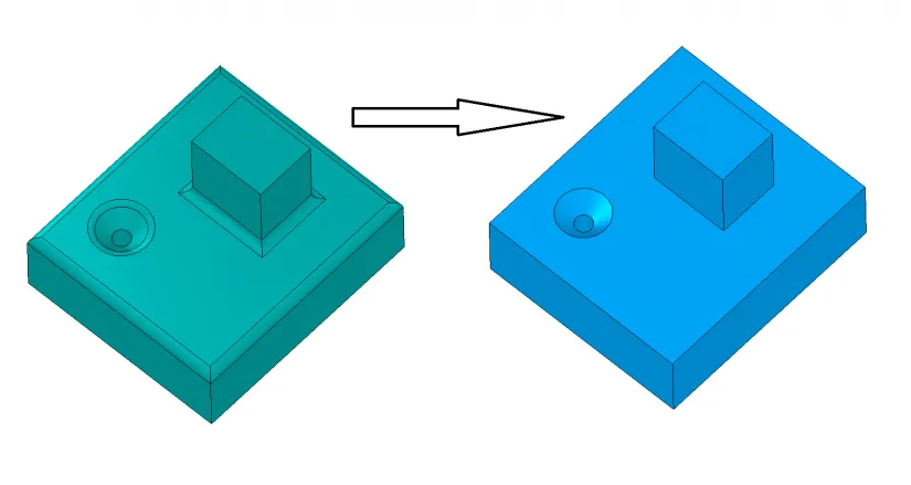
The C3D Modeler module, for instance, implements all of the operations needed for constructing 3D and 2D objects of any shape. It offers key modeling features in demand among CAE developers, such as Boolean operations, shell sections, split lines, equidistant shell construction, and direct editing. A particular highlight is our flexible methods for calculating geometry, such as when constructing triangles, calculating mass-inertial properties, and determining collisions between model elements.
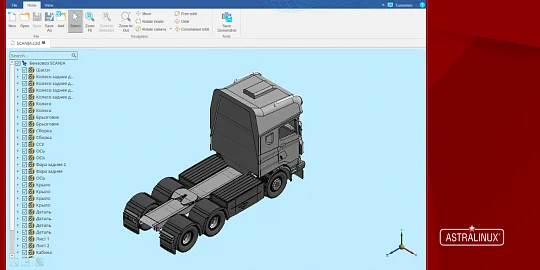
The tight integration of our C3D Modeler and C3D Converter modules means that CAE software import models correctly by including related data from standard exchange formats, such as ACIS SAT, IGES, JT, Parasolid X_T and X_B, STEP, STL, and VRML -- and then export the models and their data to other systems. This creates a high level of integration between your CAE applications and third-party software.
Initially, we had developed just those functions needed by CAD developers in the fields of engineering, construction, and architecture, just like developers of other CAD kernels. But when we signed up our first CAE customer, we implemented additional functions after listening to their needs. As a result, our C3D Modeler kernel features tools specifically requested by our customers in the CAE industry.
For example, we added the following capabilities and tools to C3D Modeler upon the request of PSRE Co. The firm uses our C3D Modeler and C3D Converter modules for its PASS/EQUIP software that performs structural analysis of pressure vessels.
- Storage of double- and float-type triangulation data
- Input of triangle parameters by angle, deflection, or maximum allowable distance between two adjacent points
- New examples of code demonstrating the rapid creation of split lines without additional construction
- Improvement of direct editing in removing fillets, chamfers, and holes
- Control of merged edges and faces in Boolean operations, cutting shells, and truncating shells
- Identify contact faces of bodies with oppositely-directed normals that have finite overlap areas
- Construct surface copies of NURBS with 2D NURBS boundary curves based on the faces of shells
In another example, we improved C3D Modeler’s FindTouchedFaces function in response to a request from Tera Analysis. We added the new SplitTouchedFaces function to detect and process situations in which geometric bodies touch each other.
We keep in close touch with our customers, constantly accepting their requests for new features, and evaluating how to implement them. In our approach, each customer gets to have the software developer tools they need, regardless of company size and income.

Author:
Oleg Zykov
CEO of C3D Labs

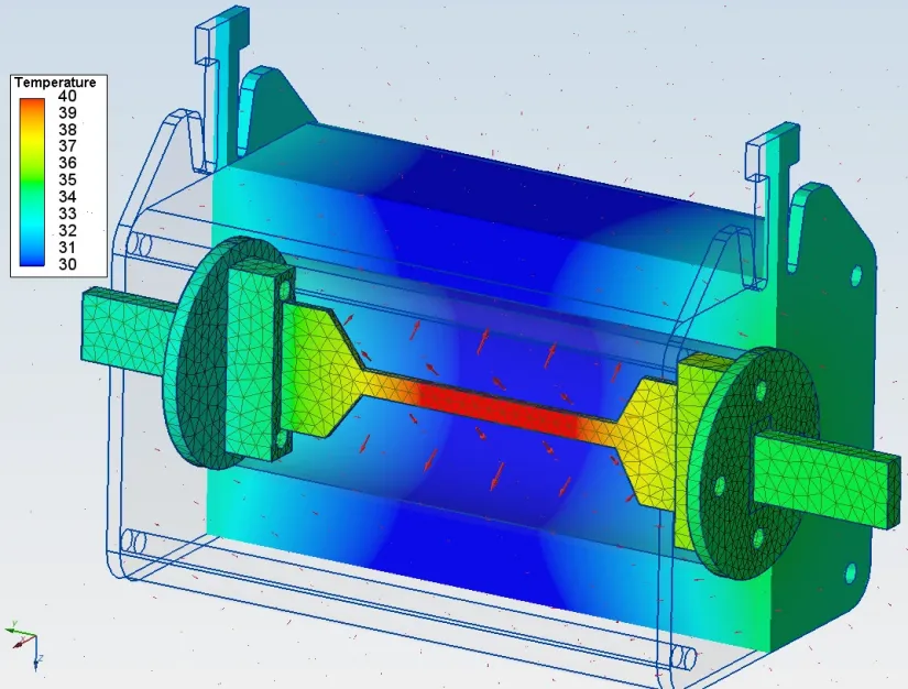




“Firstly, CAE programs need information about the incidences between faces and edges in a multibody geometry because the physical process of energy exchange occurs not only inside a body, but also across boundaries of contacting bodies.
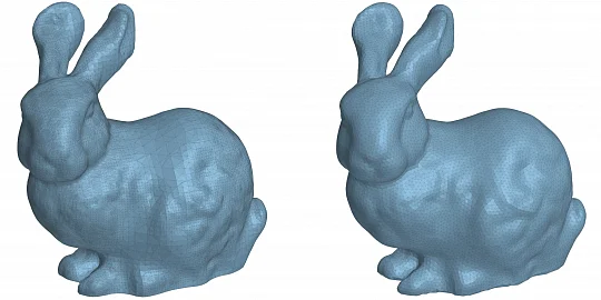
“Secondly, there is a higher requirement in the quality of face tessellations, as they are used not only for drawing, but also for transferring geometric data to the subsystem that generates finite element meshes.
“Finally, in the CAE world there are 3D models that you would never find in the design world. For example, there might be a body completely immersed in another body, or cavities inside one-piece parts. These cases occur when calculating bodies like electromagnetic fields, for which air is also a body."