Andrey Tumanin presents an overview of the key changes to the C3D Modeler kernel and talks about the team’s plans for the future.
C3D Modeler, or just the C3D Geometric Kernel, is a domestic software solution for building and editing even the most complicated geometric shapes. The kernel primarily uses the boundary representation. It also supports polygonal representation and offers a range of operations with polygonal geometry. B-Rep bodies, polygonal meshes, and wireframes may have a building log tree to rebuild the geometry with new parameters. Besides the conventional curve, surface, and solid modeling, the C3D kernel is evolving fast towards more direct and polygonal modeling features. There is also a unique sheet metal modeling module. Still, our greatest asset is our team with its 20+ years of experience and unparalleled expertise in geometric modeling.
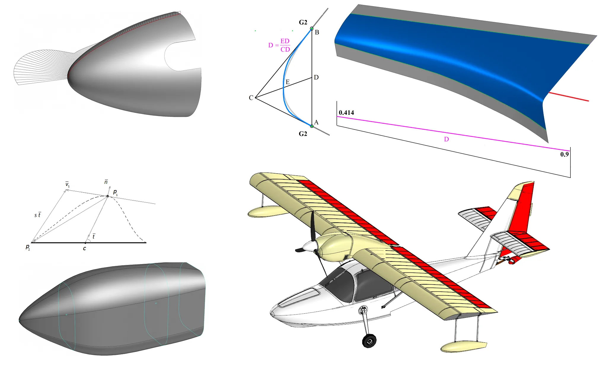
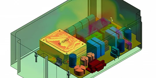
Figure 1
Let us talk about the C3D Modeler kernel development trends. File conversion inevitably results in accuracy loss and distorted geometry. There are two ways to make the resulting geometry editable. First, add diagnostics and repair tools. Second, the subsequent operations should be performed with controlled accuracy.
The demand for direct modeling has been growing recently. It is a strategic trend for the C3D kernel, as well. The interest in polygonal modeling tools is also on the rise. First of all, our current and future users need a tool to heal and manipulate polygonal objects. There is also a consistent demand for polygonal reverse engineering tools, so it is yet another strategic focus of the C3D kernel team. The surface and solid modeling tools are getting more sophisticated. C3D Labs customers need more unconventional tools not available in classic CADs. For example, FEA (finite element analysis) needs to build mid-surface shells from solids or extract beam model from a B-Rep model. All of the above are mission-critical areas for our customers. We are well aware of the tight deadlines and do our best to quickly customize the products and provide the right functionality.
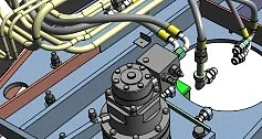
Figure 2
Let us begin the kernel change log overview from its curve modeling capabilities. Over the last year, the kernel team has greatly optimized the code. We have completed the curve extension, and curve wrapping/unwrapping functionality. The functionally defined curve has also been improved: meet a new API for creating analytical functions. The functionally defined curve documentation has also been substantially expanded. Another point: now you can optionally keep a curve parameterization as you truncate it.
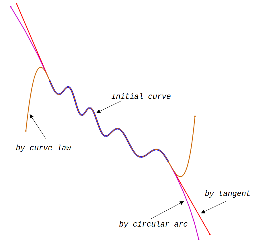
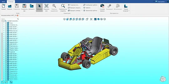
Figure 3
The contour building functionality supports tolerance at the verticesas part of the general approach to accuracy management. For instance, now you can specify the conversion accuracy in the curve-to-NURBS conversion.
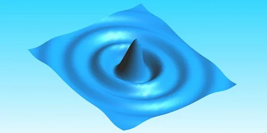
The key curve modeling functionality is constructing smooth approximated curve passing through a set of points. The inputs for this operation are the max spline deviation from the points, the order of the spline, and a flag indicating whether the spline is closed or not. Optionally, some points can be fixed so that the spline passes exactly through them. User can also control the tangent direction at these points. The effect of smoothing on the standard airfoil profile is obvious. Without smoothing, the spline passes exactly through each point, but it results in large oscillations of the curvature radius. Smoothing constructs a better curve while maintaining control over the accuracy (min distance between the spline and the control points).
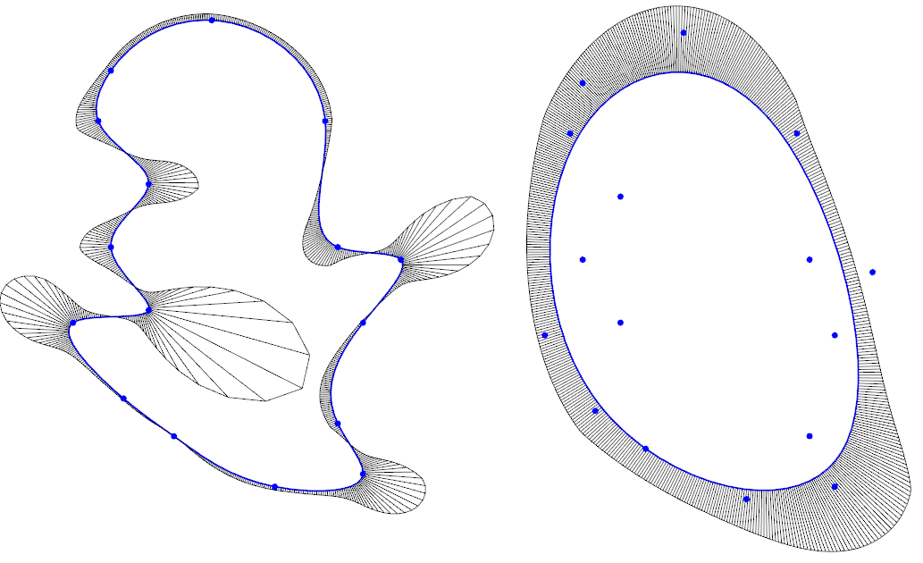
Figure 4
The curve modeling capabilities will soon be expanded to include beam model extraction from a solid shell, a new midline functionality (the points on a midline are equidistant from two parent curves in the plane), and completing the operation of line segment/circle arc fitting to a set of points.
The surface modeling updates are enhancements to the calculation of higher order derivatives for a variable conic section surface, optimization of the offset surface extension method, and significant improvements of the patch and stitch operation.
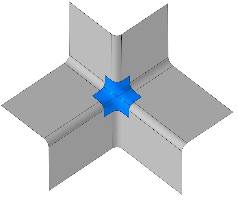
Figure 5
The mid-surface shell functionality has been expanded. Similar to curves, the surface-to-NURBS conversion can now control the accuracy, and the conversion algorithm has been significantly updated. We have managed to accelerate the approximation of isoclines through such strategies as the optimal selection of the control used to track the accuracy of the conversion. As a result, we have improved the quality of NURBS-to-surface conversion while preserving its excellent performance. The conversion of a non-uniformly parameterized surface to NURBS used to result in some distortions. This is fixed now.
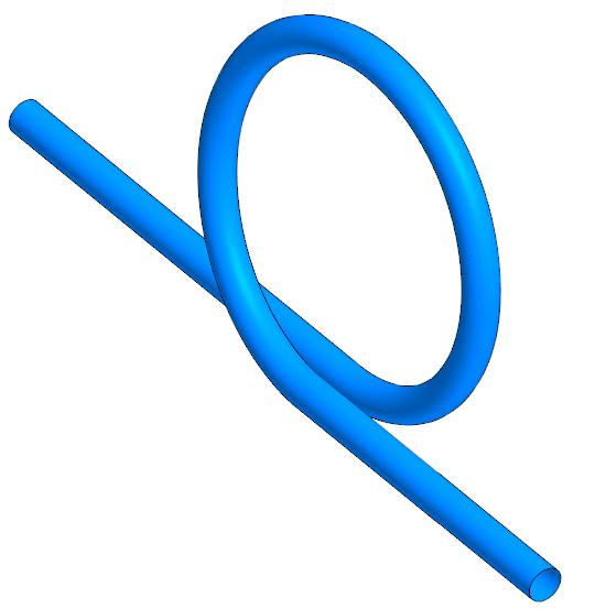
Figure 6
The most significant advance in surface modeling is a new operation to fillet non-adjacent faces. For this, we have refined the conical section surface construction with the rolling disk fillet method. The disk rolls along a given reference curve while touching two groups of faces that may be not connected. You can control the boundaries of the resulting fillet since it is a variable-radius surface. The radius can follow a linear, cubic, or even an arbitrary law defined as a curve. The reference curve can include multiple segments, while the rounded face can trim the adjacent faces along the reference curves for subsequent stitching of these faces into a shell. The user can define the side on which the fillet is built. Finally, the cross-section of the surface can be an arc of a circle or ellipse, a parabola, a hyperbola... generally, any spline smoothly joining the adjacent surfaces, or a straight-line segment.
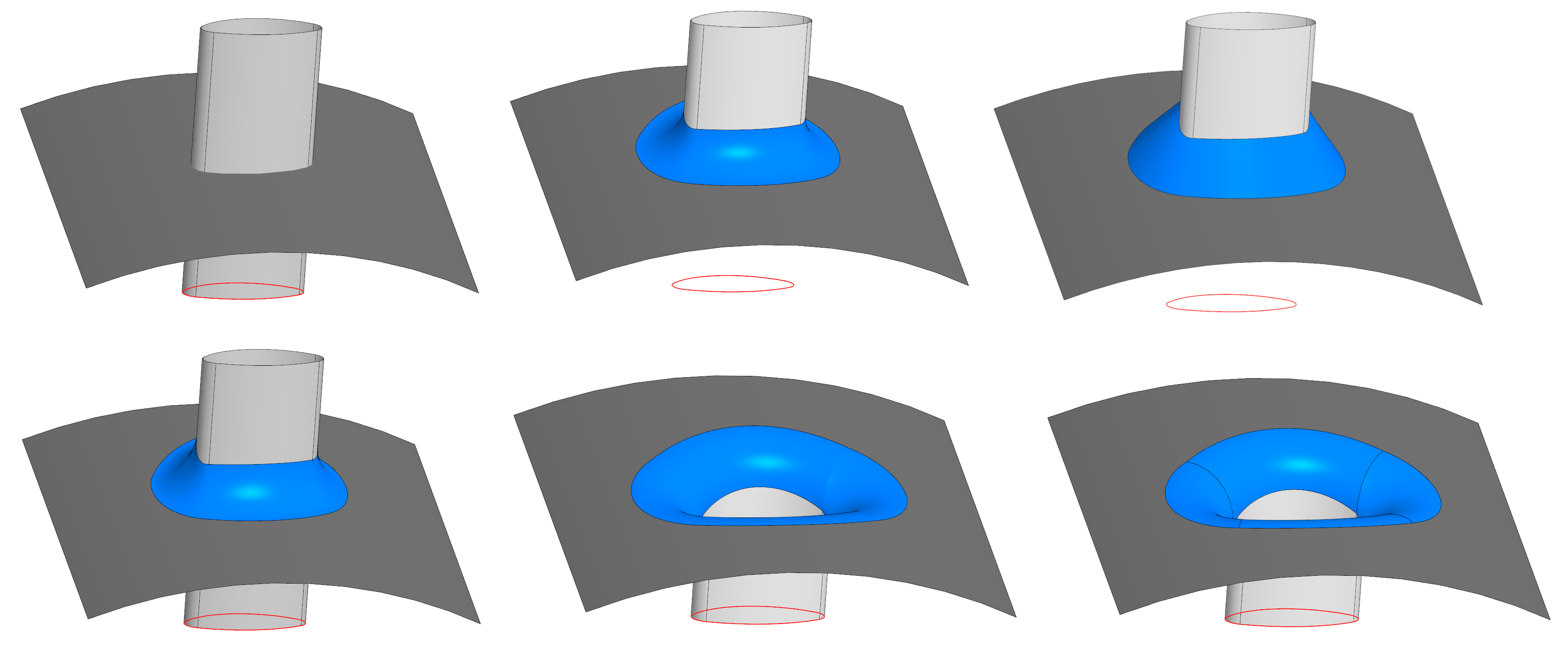
Figure 7
The surface modeling roadmap includes enhancements to the non-adjacent faces fillet operation, and adding a new surface extension function that specifies the law defining the new surface: either straight tangent or tangent with some finite curvature. We will keep refining the double curvature surface development to account for discontinuities and overlaps and to modify the patch boundary accordingly.
The new improvements to the solid modeling functionality are the input contour checks for self-intersection in the sweep operations. We have also added wireframe-type generatrix to the sweep operations and improved the nearest-body search for the tapered extrusion operation.
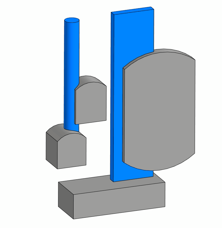
Figure 8
There is a new operation to build a taper on a continuous chain of edges of the face. The original taper operation has also been refined. We have introduced a self-intersection check. Besides, now this operation correctly handles degenerated topology after tapering. We are working hard on a basic lofting operation with a variable cross-section. This means that the parameters of a cross-section that moves along a given path can vary as functions. With this, you can model even the most complicated shapes. As mentioned above, the accuracy management features will be added throughout the year. In this period, we are also going to implement the variable cross-section lofting operation.
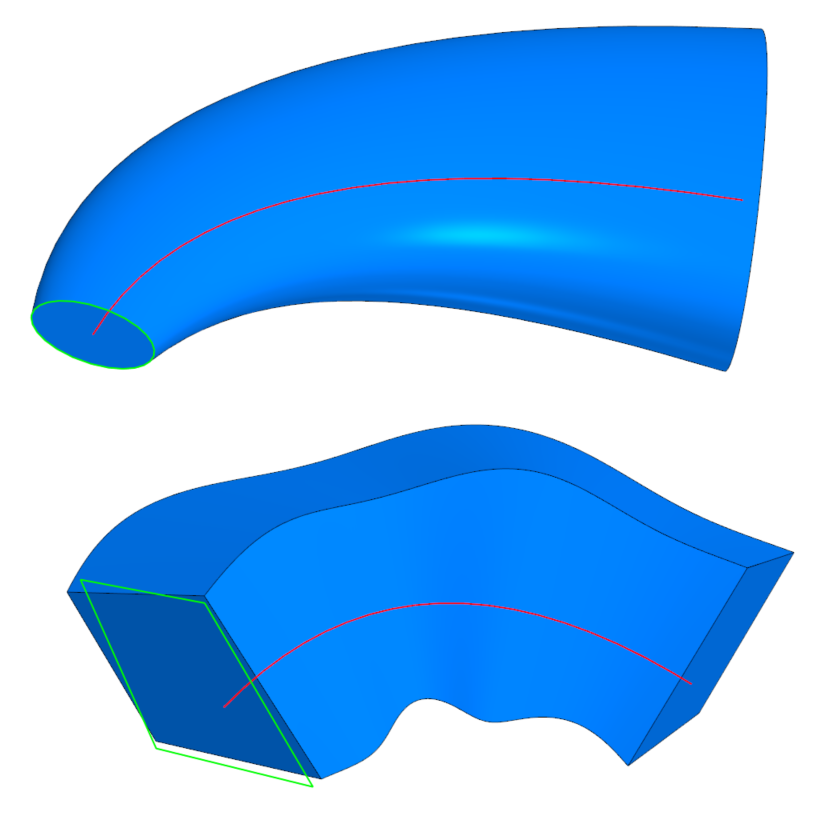
Figure 9
As to the projection module, for 2D projections, we have been working for the year to improve the construction of Silhouette curves and better break them apart. Local sections are now generated much faster, and non-cutted components are handled more efficiently.
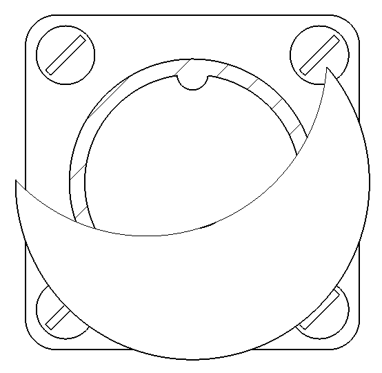
Figure 10
The centerline functionality has also been changed. The highlight of the 2D projection module is the ability to project polygonal objects. Now the projection algorithm supports not only solids but polygonal bodies as well--in any combination. The silhouette curves are built to match the polygonal objects. The overlaps between solid and polygonal objects are correctly handled. We are now focusing on the projection of triangulation area boundaries. If a polygonal object contains multiple triangulated areas, we need to be able to project the boundaries of such areas. We are going to achieve that.
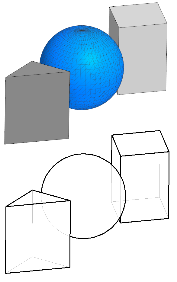
Figure 11
There is a range of general, system-level improvements to the kernel. First, we continue the transition to new interfaces. We have added a progress indicator to the operations. It not only shows progress but can also be used to interrupt long operations. This applies to both Boolean operations and triangulations. Second, we are going to make the kernel objects thread-safe. Other activities include C3D format license protection for C3D, unification of C3D and STL format objects so they can be used in range-based loops, added color attributes, and visual effects improvements. We have introduced new color conversion interfaces, and new system attributes like int32, int64, and double number vectors. Another new feature is the object-to-object distance measurement (e.g., curve-to-curve, or curve-to-surface).

Andrey Tumanin
C3D Modeler development team leader
Ph.D.
C3D Labs