In July, we released C3D Toolkit 2020, a major update to our SDK used by developers of engineering software. This post will focus on the new and improved functions of the C3D Vision visualization engine, a part of C3D Toolkit.
Being responsible for displaying geometric models and GUI operation, C3D Vision controls the quality of 3D model rendering through its math algorithms, software and hardware tools, as a result of which it accelerates 3D software applications. In the 2020 version, we focused on the three key areas.
The first important area is an optimization of user interaction processes. The following features added increase the productivity and usability of the 3D engine:
- Conversion of any representations of GUI events into the С3D Vision format
- Improvement of control and editing processes
- Ability to choose devices in user processes
- Minimization of user’s code for generating scene.
For operating with geometric representations and geometric objects, new abilities have been added.
- Additional geometric representations
- Brand new geometric objects to operate with two-dimensional arrays
- The extension of geometry properties.
Such abilities are intended to provide developers with additional functionality when constructing, editing, drawing, and converting geometry.
Finally, we improved the tools for zooming, frame-based object selection, plane-based section, etc.
Now, let’s get a deep dive into the updated C3D Vision to discover a host of new visualization features.
Filtering Events from Physical Devices
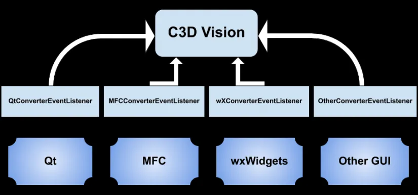
In each visualization library, such as Qt or MFC, describing and representation of events are performed in their own format. That’s why, C3D Vision provides the ConverterEventListener filter – a special tool for operating with any libraries. Its main objective is to convert a representation of GUI events into the C3D Vision format. As a rule, the event source is a graphical window where the whole scene is rendered, however, other system objects can act as events, like a control or the main window. To illustrate interaction between a user graphical interface and C3D Vision, you can use the known libraries as examples, and event sources.
Improving Processes of Controlling and Object Editing
In the new version of C3D Vision, the scene updating and the event processing are synchronized. For example, when moving a mouse and rotating the entire scene, a frame is updated after its preparation. This provides smooth rendering while any manipulating with objects, or the scene. Besides, when using various physical devices used in the process any events are now homogeneous. The presented diagram shows this.
In this case, the process works with two event sources -- a keyboard and a mouse translating homogeneous events into the process. For example, it can be a shift along the X axis. Together, this allows using certain templates in the code.
Defining Devices in User Processes
C3D Vision 2020 provides an ability to set event sources that are necessary on a case-by-case basis, when creating your own processes.
These devices can be customized on your own. You can set certain keys for the assigned devices to perform an action during the process. For example, the D key of keyboard activates move along the Х axis, the Ctrl + arrow key shortcut activates object rotation around the selected axis, etc.
Minimizing User’s Code to Generate Scene
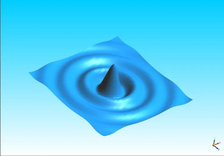
Integration of C3D Vision with the C3D Modeler geometric kernel is implemented with two classes -- MathRepresentation and MathGeometry -- operating directly with the math representation MbItem.
This relationship allows you creating specific templates to generate visual representations. The code performing this is rather laconic.
// create math representation
SPrt<MbSurface>* mathRep = createSqrtSinSurface();
// create visual representation
GeometryRep* visRep = SceneGenerator::Instance()->
CreateMathRep(mathRep, MathGeometry::Synchronous);
// create segment with specified parent
SceneSegment* segSurface = new SceneSegment(visRep, topParent);
Additional Geometric Representations
Set of simple geometric objects has been extended and finalized. These objects can be applied in tools separately, and together as well.
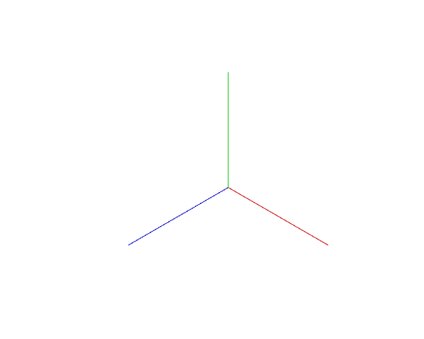
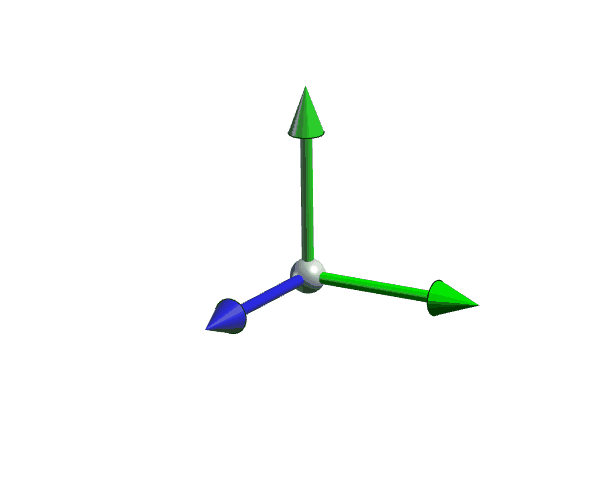
The new geometric object added is an origin with ability to select its primitives. They can be used as underlying objects while modelling. As you can see in the figures, origin has two representations, simple and volumetric.
Markers and Icons
The 2020 release of C3D Vision added the new geometric representations such as markers and icons, including:
- Geometric icons based on images of various formats
- Symbolic and frequently used icons.
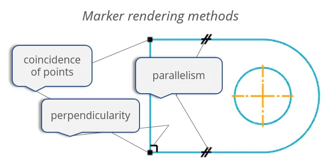
Standard set of markers has been developed to mark limitations. If necessary, you can create your own representations using the Painter tool.
Height Map
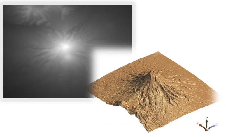
Along new implemented tools, geometric object HeightMapSurfaceGeometry goes, that allows operating with a two-dimensional array of a height map. As you know, the array can be represented using images of .png or another format. Thus, height map allows to calculate values for all three coordinates both automatically and manually.
Sketch and Label
Sketch and label are the new plane-based objects. MathSketchRepresentation and MathSketchGeometry classes are developed to display an array of two-dimensional curves that are inherited from MbCurve. LabelRepresentation and LabelGeometry are developed to display a text with adjustment of image orientation.
New Rendering Features
In C3D Vision 2020, really extensive changes have been made to improve and finalize the features capable of rendering geometric objects.
- ScreenPlaneOnly allows a specific geometry to set a rendering mode in the screen plane.
SceneSegment* planeScreen = new SceneSegment(pTopParentSegment);
planeScreen->AddFeature(new Feature::ScreenPlaneOnly);
- NoScalable sets segment geometry unscalable, not depending on the overall scene zoom.
SceneSegment* noScalableSegment = new SceneSegment(pTopParentSegment);
noScalableSegment->AddFeature(new Feature::NoScalable);
- DoubleSidedLighing takes control to set two-sided lighting to a specific geometry, not depending on the overall scene lighting.
SceneSegment* doubleSidedLighting = new SceneSegment(pTopParentSegment);
doubleSidedLighting->AddFeature(new Feature::DoubleSidedLighting);
- RenderMode displays the selected geometry in a specific mode (tone, half-tone, wireframe, etc.).
SceneSegment* renderModeSegment = new SceneSegment(pTopParentSegment);
renderModeSegment->AddFeature(new Feature::RenderMode(rm_Wireframe));
- SectionPlanes mode allows to set a section of selected segments by the plane. In the picture, the section by the plane is set only to the part, and ignores the cube.
SceneSegment* sectionPlanesSegment = new SceneSegment(pTopParentSegment);
sectionPlanesSegment->AddFeature(new Feature::SectionPlanes(12));
- FaceCulling is necessary to optimize rendering of a complex geometry; it allows rendering not the assigned faces, but those that are not visible to the user, or vice versa. This is defined by the flag when creating the object in FaceCulling. In the given example, the front edges are not rendered.
SceneSegment* faceCullingSegment = new SceneSegment(pTopParentSegment);
faceCullingSegment->AddFeature(new Feature::FaceCulling(bool back));
Layer Rendering
RenderLayerSettings structure allows setting for a specific layer such rendering modes, as lighting, material, and rendering type. SetRenderLayer function defines a layer number for a scene segment. The first parameter is a layer number, and the second one is a flag for distributing layer rendering to child segments.
SceneSegment* pSegment = new
SceneSegment(pTopParentSegment);
pSegment ->SetRenderLayer(1, false);
New and Improved Tools
C3D Vision 2020 supplies the improved tools for direct editing of geometric objects.
The PrFindSelectArea tool selects geometric objects using a frame. The ability to select both unifying and cutting frames, and their combinations as well - from left to right and from right to left is added.
The object zooming gets to have its additional features extended. Zooming now can be performed using a frame. The PrCameraZoomBox tool has settings depending on the user’s configuration.
CoordLocator is a new tool developed to convert coordinates from physical devices, like keyboard, as a rule, in editing processes.
The updated C3D Vision delivers three types of locators:
- ModelCoordLocator is a conversion of coordinate values into model coordinates
- SurfaceScreenCoordLocator is a conversion of coordinate values into a given surface
- CurveScreenCoordLocator is a conversion of coordinate values into a given curve.
Interactive Manipulators
Another key area of C3D Vision development is implementing interactive tools used to edit geometric objects. Here are enormous changes made and new features implemented.
In particular, CuttingTool, a dynamic section by the plane, has been improved. Now you can control plane position with interactive tools: move and rotation manipulators.
One of the most important innovations regarding interactive tools is implementing manipulators. The base class of manipulators is called SceneWidget used both separately and as a part of object editing processes. It represents a kind of wrapper, including the processes to ensure its behavior, as well as a model of representation on the screen. Processes describing SceneWidget behavior can be initialized with locators that will determine the manipulator behavior.
SceneWidget for manipulators provides standard behavior processes and their models implemented, that cover about 80% of the necessary solutions:
- Hot-point is a widget with a specific representation and behavior
- Move manipulator makes a move by the specified axis
- Rotation manipulator makes a rotation around axes.
Our team makes a lot of efforts to ensure that C3D Vision meets the highest requirements of users. In the near future, our plans are to solve the following tasks:
- Developing materials with support and use of shaders, including a standard set of materials based on the .JSON text format
- Developing OcclusionCulling, an essential function providing optimal performance for rendering complex models
- Creating time-dictated cloud-based solution of our component with preserving the maximum possible similarity of the API with Vision and providing a familiar environment for both experienced library users and beginners.
We keep working on improving our visualization engine, so in the next version, you will see another new tools and additional features aimed to quickly create engineering software applications.

Author:
Artyom Maksimenko
C3D Vision Team

