Sergei Galtsev, a leading software engineer in ASCON’s Application Development Department, discusses the KOMPAS-Composites application and its use of polygonal modeling tools.
A composite is a material composed of a reinforcing filler and a binder. A good example is fiberglass cloth impregnated with epoxy resin. There are many composite products available. ASCON’s products help design components manufactured by laying up layers of fiber in specific orientations. One material we use is carbon cloth. Such a structure offers durability, structural strength, and precision to meet the stringent requirements of aircraft, helicopter manufacturing, mechanical engineering, and other industries. The products operate in harsh or high-speed environments, such as in aerospace applications.
One such product is the aircraft engine. It has a damper made of laminated polymer composite. The damper features many transitions and folds forming a complex, curvilinear shell.
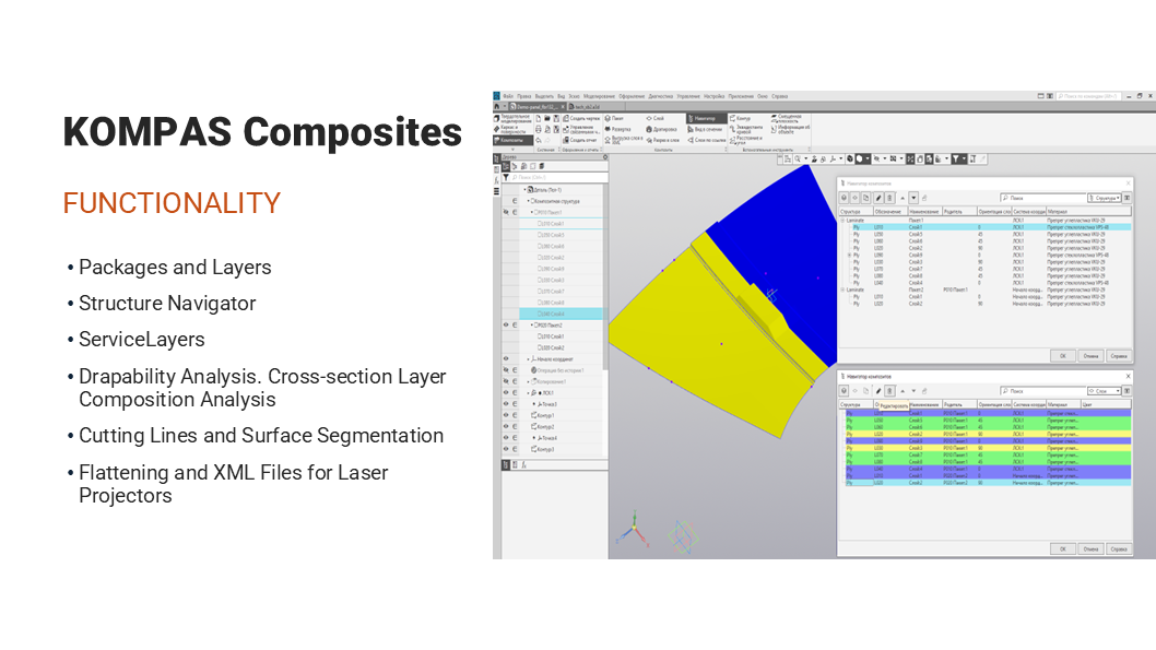
Fig. 1
In our CAD application, we design such products layer by layer. The designer imports or builds some complex surface with folds and transitions in a CAD tool. Then we add curves running along the surfaces, make groups of layers, and finally construct the boundaries for each layer in each group. A design model is made in this way. Then the model is delivered to manufacturing engineers. They prepare the manufacturing process for making the layers. The manufacturing layers are generated from the layers defined by the designer. The manufacturing engineer analyzes these layers, creates manufacturing operations, and produces flattened patterns to be sent to the cutting machine. Next, they prepare files for the projector which guides the layup process as the final part is made.
Our application also has a built-in Navigator to handle composite objects in KOMPAS CAD.
Now let me tell more about how we use the polygonal modeling tool in our application. In fabric modeling, the challenge is to simulate the behavior of the material put on a complicated surface. The goal is to prevent layup issues such as folds and stretches.
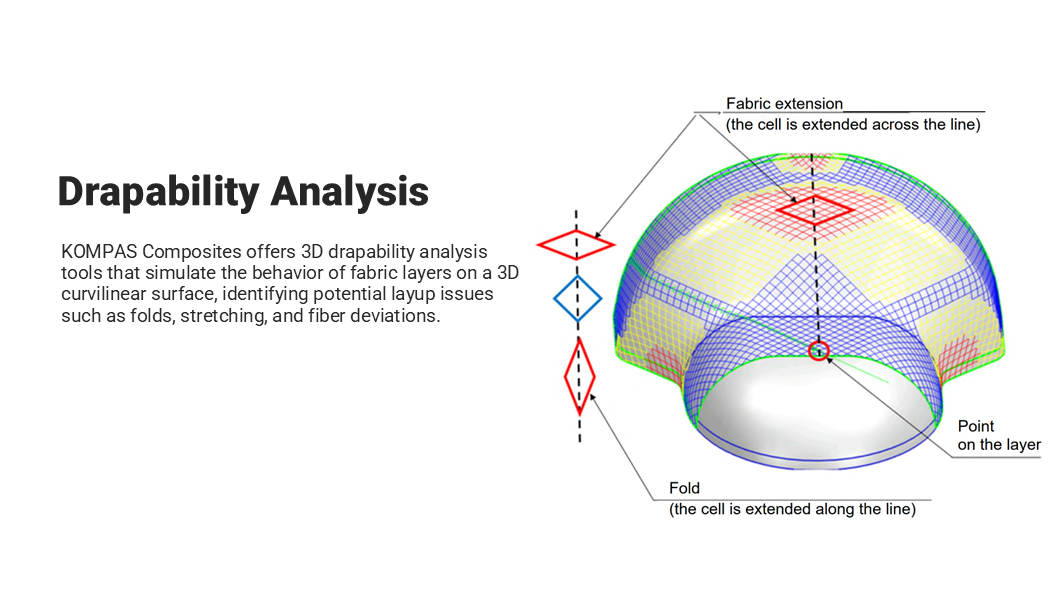
Fig. 2
The first problem is drapability analysis. Its result is a color-coded 3D mesh. The colors represent the deviations of the fibers. The figures show differently shaped mesh cells. To build such a color map, we need to measure the cell deflection angle and compare it to the maximum threshold specified for the particular material.
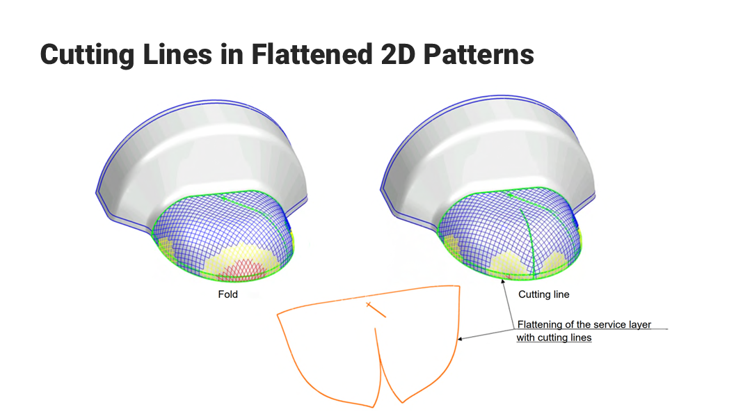
Fig. 3
The second problem is designing cutting lines and flattened patterns. The drapability analysis on the image 4 indicates a fold (red area). We need to produce a smooth outline of the 2D flattened pattern with a cutting line.
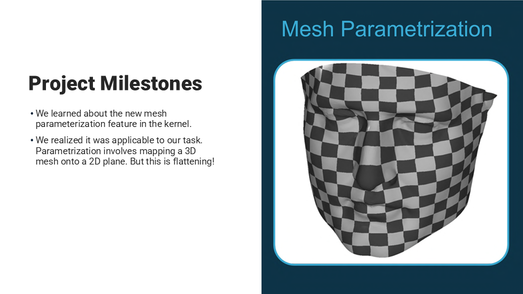
Fig. 4
I would like to share the history behind our product. A year ago, we learned about the new mesh parameterization feature in the C3D kernel. What is parametrization? It is a mapping of the mesh to the plane. In other words, it is a flattened pattern. We can claim that the best-known application of parameterization is fitting shells onto complicated surfaces.
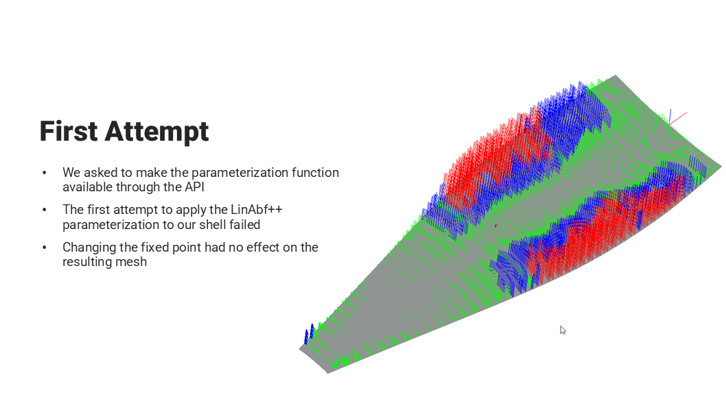
Fig. 5
At that point, we decided to incorporate 3D polygonal modeling tools in our application. For this, we asked the KOMPAS team to make the parameterization functions available through the API. However, when we applied the LinAbf++ parameterization method to our shell, it failed: moving the fixed point did not affect the final mesh. It was very important for us: of all the surface points we needed to choose a layup point to minimize the number of red areas in the models. Every red area requires a cutting line, and unnecessary cuts are undesirable.
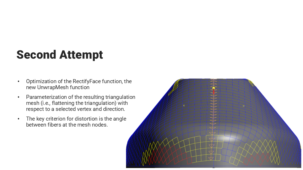
Fig. 6
Our next attempt was the optimization of the Rectify Face function and a new Unwrap Mesh function. It takes a coordinate system as an argument to specify the layup reference point and the warp direction to estimate possible deformations. It also calculates the key distortion estimate: the angle between the cell sides compared to 90 degrees. This picture 7 shows the original mesh and its issues. The first problem was that the mesh did not reach the surface boundary. The flattening produced a jagged, incomplete mesh boundary. The second problem was that we obtained asymmetric (with respect to the layup orientation) quads on symmetric models. Such a model would have folds on both sides, but the mesh did not reflect that.
As our interest grew, we doubled our efforts and asked the polygonal modeling team at C3D Labs to solve our problems.
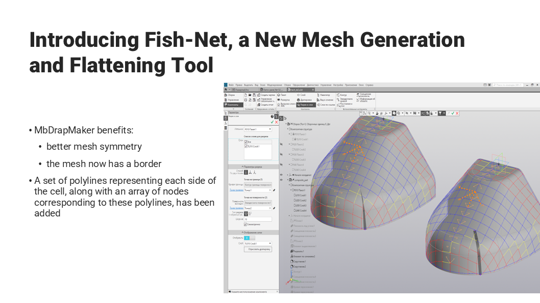
Fig. 7
The currently used mesh is built using the FishNet algorithms and MbDrapMaker. It has become more symmetrical on symmetrical models and now has a smooth boundary.
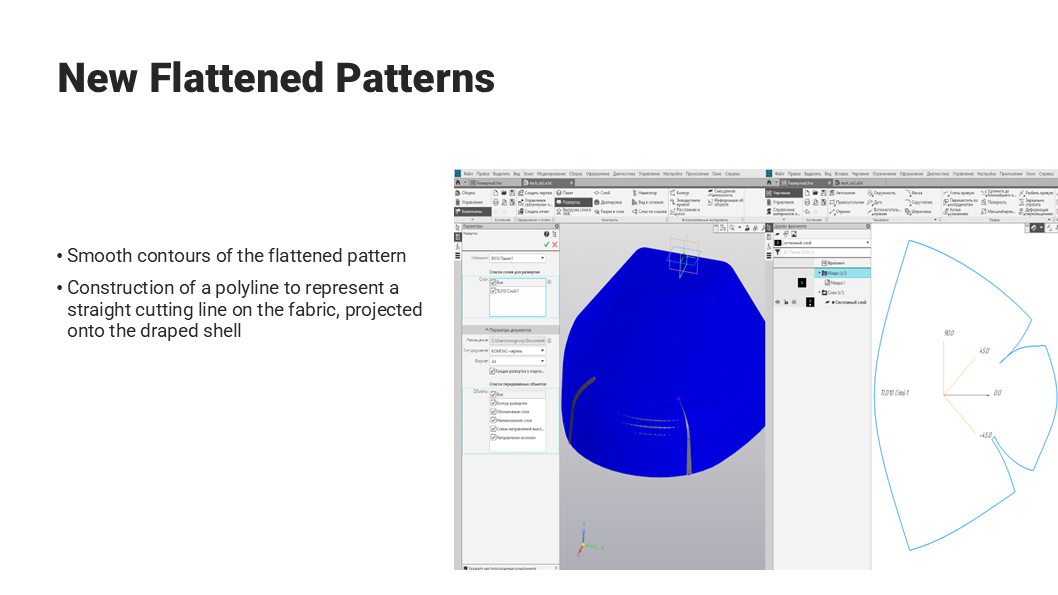
Fig. 8
Look at the smooth edge of the flattened pattern with two cutting lines. It is no longer jagged and looks sufficiently smooth.
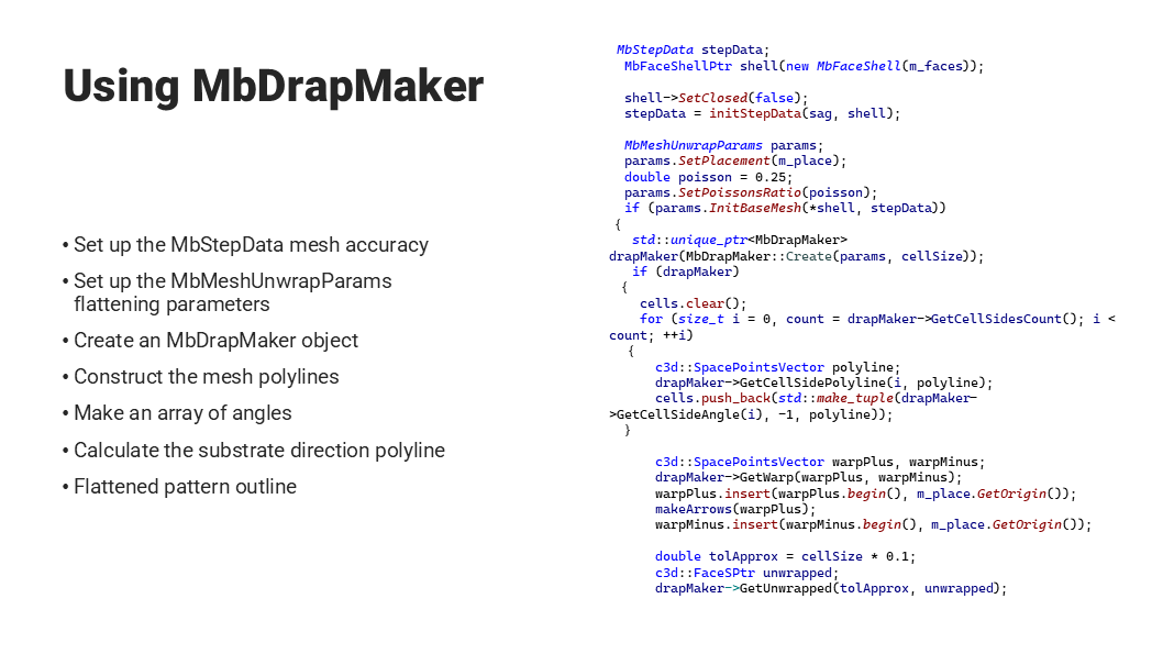
Fig. 9
Our current workflow is: we set up the mesh accuracy and flattening parameters, create an MbDrapMaker object, get an array of angles along the mesh line, and for each line, calculate the warp orientation and generate the flattened pattern.
We are going to add more layup strategies. Today, we support just one layup strategy: mesh points are propagated away from the reference layup point. That is, we take a point, draw the warp and weft directions from it, then progress along geodesic lines in all directions, find the fourth point from the three points, and so on. In this way, we construct the mesh cell by cell and cover the entire surface. We need other strategies to minimize the number of red areas. When applied to different models, such strategies produce different numbers of red areas. The MbDrapMaker object also needs to be improved. So far it cannot handle complicated flattened patterns and often produces discontinuities and asymmetric curved meshes. We look forward to C3D Labs and waiting for the new releases of their polygonal modeling tools.

Sergei Galtsev
Leading software engineer, Application Development Department,
ASCON