This is the final part in a series of papers that talk about a new type of curve and surface modeling developed by C3D Labs.
In our first article, we covered the essentials of fair curves, explaining the benefits of this class of curve, and described its applications to engineering geometry. In the second part, we presented how we expose F-curves in C3D Modeler.
In this part, we give examples of how C3D FairCurveModeler benefits modeling in the real world.
Real-World Applications of С3D FairCurveModeler
Advanced CAD systems that model complicated curves and surfaces are used extensively for product development in numerous industries. Still, even when CAD systems can model class-A curves and surfaces, they may not be able to provide the smoothness expected from so-called functional curves.
The developers at C3D Labs faced the challenge of how to offer customers of their software development kit top quality curve and surface modeling. A series of geometric modeling studies resulted in C3D FairCurveModeler, a new component of the C3D Modeler kernel designed to model class-F curves.
Let’s take a look at examples of how the new curves benefit design outcomes.
С3D FairCurveModeler Case Studies
Smoother geometry leads to better performance. One way to get smoother geometry in product designs is with our C3D FairCurveModeler. It is a fast and affordable way to improve product specifications.
As a rule, when optimizing designs, the priority of one property is maximized to the detriment of other properties. A better optimization strategy maintains the other properties within specified ranges, and this is the approach we took optimizing product performance in the case studies that follow.
Modeling Better Plows
To improve their performance, plows are equipped with “shark fins” to help them till the soil. The fins, however, incur a higher plowing resistance, which results in higher tractor fuel consumption. Could we design a fuel-efficient plow?
We optimized the geometry of a standard plow design. The plow design was extensively analyzed with FlowVision CFD (computational fluid dynamics) from TESIS, both lab- and field-tested. The new design resulted in better plowing performance and lower fuel consumption.
These results were positive, but they puzzled us. The smoothness of the plow’s leading edge curve was improved, and as a result the entire plow surface became burr-free.
Cam Modeling
Cams are used by industry to change rotation to a back-and-forth movement that can even pause movement, such as in automobile engines. There are, however, two issues with modeling 2D cam profiles:
- Curves in the cam dwell section should be circlular arcs
- Follower up/down sections should smoothly blend with the dwell section curves; to avoid jerks, the order of smoothness should be at least 3
Could cam design benefit from functional curves?
The designer combined smooth curves to implement the required valve timing. Its methods generated exact conic curves and produced even 9th-order smoothness of transition curves. C3D FairCurveModeler successfully solved both problems.
Turbine Vane Optimizing
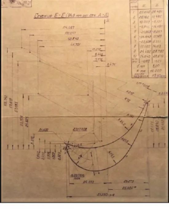
Standardized vane airfoil profiles are available in industry databases. The design of these standard profiles are the result of a tremendous amount of work in optimizing macro properties. Such vanes are the golden eggs of steam turbine manufacturing. Could steam turbine vane modeling benefit from functional curves?
C3D Labs experimented with new designs, analyzing them with the KompasFlow CFD plugin for KOMPAS 3D CAD design software. We changed only the geometry while preserving the specified macro property values. The experiments resulted in better vane geometry.
- - -
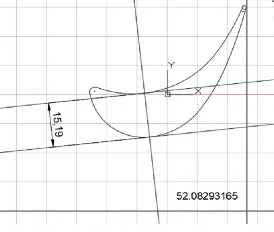
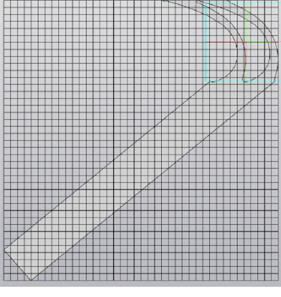
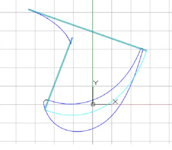
A vane airfoil profile is a complex curve made of circle arcs.
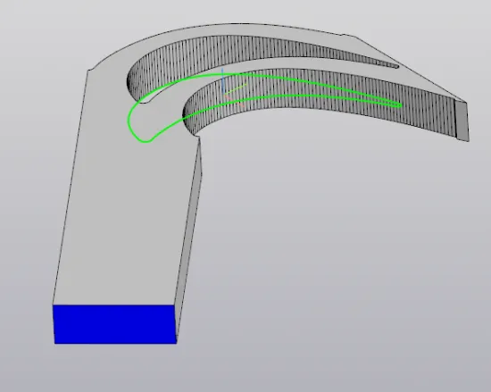
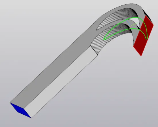
We used the profile shown in the illustration above to build a model for analysis in KompasFlow. The inflow direction is along the inlet wedge angle bisector.
As turbine wheel have many vanes, the model incorporated vane-to-vane gaps and adjacent vane profiles. The vane pitch was 20mm.
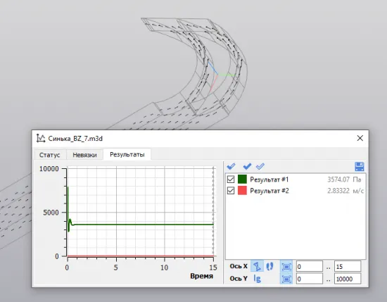
Auxiliary planes were added to visualize the vane properties. A horizontal plane 5mm from the OXY-plane displayed the velocity vectors, while an auxiliary plane coincident with the trailing edge displayed the results. The criteria we used to determine improvements were average outlet velocity and total outlet pressure.
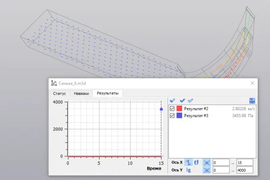
A KompasFlow analysis produced the following values for the original design:
- Average outlet velocity: 2.80226 m/sec
- Total outlet pressure: 3455.98 Pa
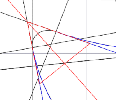
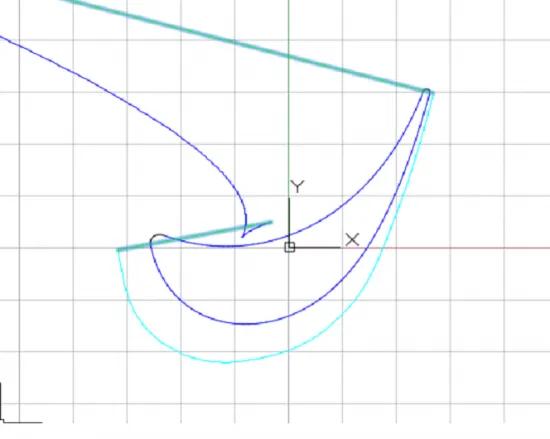
We theorized that a smoother vane profile should lead to better performance, while maintaining the initial macro properties. So we modified the vane suction and pressure side curves with the high-quality (in terms of smoothness) curve generation features available in our C3D kernel’s FairCurveModeler module.
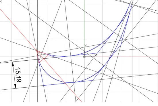
We used the “V-curve on tangent polygonal line” command to draw tangents at arc junctions and to modify profile curves. The profile curvature plots are smooth.
We reanalysed the 3D model, replacing the initial suction/pressure side curves with the new ones. All other analysis settings were left unchanged. The modified vane offered better performance.
- Average outlet velocity: 2.83322 m/sec (up from 2.80226 m/sec)
- Total outlet pressure: 3 574.07Pa (up from 3 455.98Pa)
The KompasFlow analysis revealed that smoother vane profiles designed with our C3D kernel’s FairCurveModeler methods improved vane performance significantly. This, and the other case studies listed above, lead us to believe that product performance optimization through smoother functional curves looks very promising.
Summary
The case studies show that C3D FairCurveModeler is a promising technology for better industrial design. The functions of C3D FairCurveModeler, C3D Modeler’s new module, can generate high-quality smooth curves that meet the strict smoothness and aesthetics requirements of engineering curves.
Geometry refinement is an easy, affordable way to significantly improve product performance.

