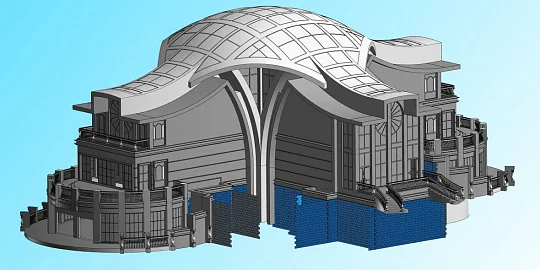
Andrei Tumanin, Ph.D., Head of the C3D Modeler Development Department, C3D Labs, talks about the general trends of the C3D Modeler kernel, new products, and plans for the future.
The C3D Modeler geometric kernel is a completely Russian software solution that can create geometric models of any complexity. To date, C3D Modeler offers the widest range of functionality in wireframe, surface, solid, sheet metal, direct, and polygonal modeling.
No wonder the C3D Modeler team has been facing many new challenges. Some of these include user requests to add new, often complex functionality. Another challenge is to quickly respond to the growing number of user requests. The development team does its best to meet these challenges.
For instance, we have significantly expanded and restructured the team. The next trend is the so-called local tolerance modeling, which gave a new boost to wireframe modeling in 2023. One more trend is expanding the kernel capabilities in complex surface modeling.
Since 2022, the C3D Modeler team has increased by more than a half. The growth since 2020 is even more impressive: the team has doubled. We have also restructured the team. We have introduced two distinct areas: polygonal modeling and direct modeling. It has resulted in two new sub-teams, while the rest focuses on the kernel’s basic functionality.
Local tolerance modeling deserves special attention. So, what is geometric tolerance? Most geometric kernels use a small “precision” or “error” value when solving fundamental geometric problems, such as finding intersecting or coinciding objects. Tolerance means some relaxed precision, a value greater than the default kernel precision.
Users may often encounter such tolerant geometry imported from third-party systems. It can also be generated by some kernel operations if the precision exceeds the default kernel value.
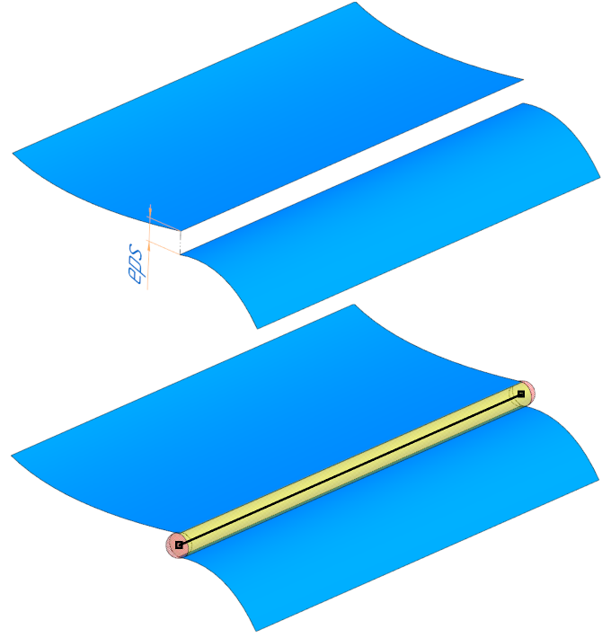
Consider an example. We have two surfaces we want to stitch into a shell. The problem seems quite simple when the surfaces intersect. If there are no intersections, we need to extend the surfaces and find their intersection. However, in most cases, the surfaces almost intersect, but it is not an intersection in the strict sense. To construct the intersecting edge, we need to assign some tolerance to it. This eliminates the conflict between topology and geometry, resulting in a topologically valid model.
Note that tolerances are associated with topology rather than geometry. For example, the tolerance of a vertex is represented as a sphere with the center on this vertex and a radius equal to the tolerance value. Similarly, the tolerance of an edge can be represented as a tube with a radius equal to the tolerance value. In general, this approach provides modeling flexibility and relatively easy geometry exchange between different systems. It is also a foundation for reliable wireframe, surface, and solid modeling.
Our important, albeit not always visible, work on the kernel’s support for local tolerances is in progress. We have already solved a user-suggested problem. We needed to construct basic objects for subsequent operations from some tolerant geometry. In other words, if there is a certain face with tolerant edges, we need to create, for example, a generatrix for the extrusion operation from these tolerant edges. The issue was that the input curves of the extrusion operation did not contain any information about tolerances. Therefore, the operation cannot retrieve even the basic object properties, and cannot check whether the generatrix is closed or not, not to mention any subsequent Boolean operations.
One way out is to use a new object which contains both curve geometry and tolerances. Such an object within the C3D Modeler kernel is the MbWireFrame 2D wireframe.
Now the kernel operations take both curves and wireframes as inputs. The wireframe can be used as the generatrix for the extrusion and rotation operations, or as the path in the lofting operation. Generally speaking, a wireframe can be both a 3D contour and a contour on a surface. In the latter case, the surface information can be added to eliminate ambiguity.
The wireframe entities also required some refinements. In particular, it concerned building contours from the wireframe while incorporating tolerances. We have added several new wireframe operations like wireframe fillet, extension, truncation, and point projection onto the wireframe. These operations are counterparts of similar curve-based operations. The key difference is that they use tolerance values.
Since wireframe operations are stored in the history tree, we have implemented all the operation builders. Besides, we have added a simple wireframe builder similar to the simple solid builder. Let us learn more about the wireframe fillet operation using the example shown. The fillets at three of the four vertices overlap because the requested fillet radius exceeds the tolerance value in the vertices. The fillet operation fails at the fourth vertex since the user provided a radius smaller than the tolerance value at that vertex. We have been intensively working on adding more wireframe operations. This project will continue until the end of 2024.
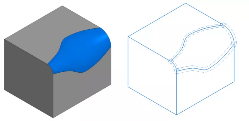
Complex surface modeling is another priority area. Let us take a look at the sweep operation with a dynamic cross-section. It is a new operation for the kernel, which we added recently. Its key feature is that the user can create and modify cross sections. This allows you to create very flexible and interesting scenarios for building complex shapes with a single operation. For example, a C3D Modeler user has used C3D Solver, another C3D Toolkit component, to manipulate the generatrix properties. Any constraints can be applied to the generatrix, e.g., linear dimension, radial dimension, tangency, perpendicularity... Still, the most important constraints are applied to the generatrix and external curves or surfaces.
The figure shows the result of a sweep operation with a dynamic cross-section. The cross-section properties are specified at certain points of the path, while some linear dimension constraints are applied to the semi-major axis of the generatrix ellipse. A more complex example is shown on the right. It is also a sweep operation with a dynamic cross-section. The segments of the cross-section have tangency constraints with the external objects. That is, the segments must touch the cones, and one segment has a linear length constraint.
The changes to the kernel are not limited to this. Besides the ongoing improvements and optimization, other updates have been made. Consider the beam element used in wireframe modeling. This functionality is particularly appealing to CAE developers. In essence, we need to build a beam representation of a solid: construct the beam curve and automatically recognize its cross-section. For this, we have been refining the Boolean operations with regions in terms of accuracy. We have also introduced new meta-spline construction options with fixed control points and tangents to these points. We have significantly improved the quality of the resulting spline in some special cases.
In surface modeling, we are focusing on refinements in constructing surfaces over a lattice of curves in terms of using such curves to separate the shell and considering local apices. We have invested serious efforts into the filleting of non-adjacent faces to boost performance and improve the quality of the resulting geometry.
The edge extension feature has also gotten many refinements. As to solid modeling, we have been improving the edge fillet operations. In particular, we have optimized the face fillet algorithm. In the Taper operation, we have implemented boss flowing and hole trimming, which significantly expands the applicability of this algorithm.
Now about the general kernel improvements. On the user requests, we have added support for symbolic expressions to the parser. We have also implemented a new workflow for handling color and visualization attributes. Another significant area of work is C3D format read/write multithreading, provided that each thread has its instance of the read/write class.
A closer look at our 2024 roadmap reveals that we are focusing on the above-mentioned tolerance geometry and wireframe operations. We will continue to refine the controlled precision of the kernel operations. In 2023, we implemented the rolling disk method. A disk rolls along some reference curve while touching two sets of faces. In 2024, the team is tasked with the implementation of the rolling ball blending method which does not require a reference curve.
We are also working on filleting butt ends, support faces, and non-adjacent faces. One more important task is constructing a mid-shell for a pair of non-equidistant faces. We are going to construct an approximated mid-surface between two non-equidistant faces using a point cloud. These points are the centers of the spheres touching both faces simultaneously.
A large chunk of work involves the geometric array of faces. The task is to copy the selected faces according to a certain pattern in such a way that by trimming or extending them it would be possible to glue them to the solid body shell.

Andrei Tumanin,
Ph.D., Head of C3D Modeler Development Department
C3D Labs

