This is an overview of the most prominent new features of the C3D Modeler geometric kernel introduced over the past year. The paper covers wireframe, surface, and solid modeling, as well as system functions and plans for the future.
Wireframe Modeling
We continue integrating wireframes into curve operations that previously supported only the curves themselves. You can now specify an external accuracy. Handling of local tolerances in the geometric model has also been improved.
The reason for these changes is that curves alone cannot convey tolerance information. In most geometric kernels, such information is available only at the topology level. Here is a simple example. Suppose we want to project a curve onto a shell, and then split the shell along the projection curve. There may be issues if the projection curve falls on a tolerant edge (an edge formed by surface curves that do not coincide within the kernel’s default accuracy). In this case, the projection may result in mismatched curves and will lead to shell split problems. There are several ways to solve this. The first option involves wireframes: the projection operation creates a wireframe with tolerant vertices. The second option is to increase the tolerance of the split operation.
These operations have been modified to support the above-listed features.
The operation for offsetting curves along faces can now process and generate wireframes (Fig. 1). A key change is creating an offset curve along a set of connected faces; previously, only a single face was supported. Another new feature is trimming the resulting wireframe with the boundaries of the faces involved, or extending the wireframe to those boundaries.
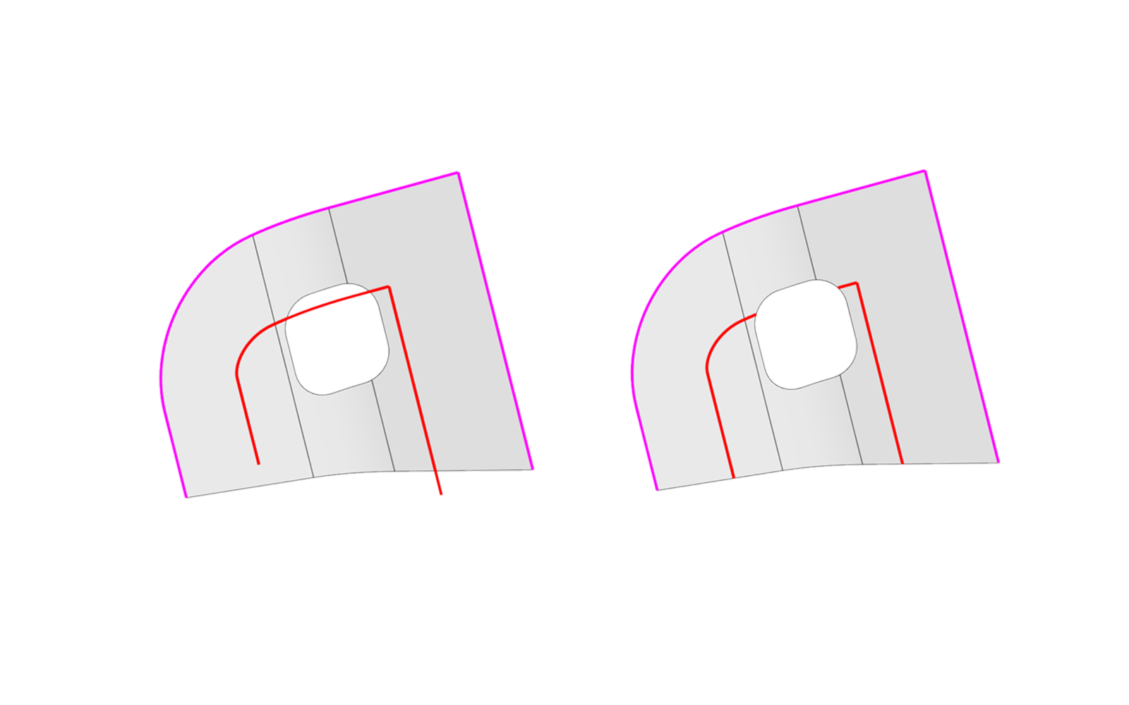
Fig. 1. Offsetting multiple faces.
The wireframe projection operation can now handle wireframes and local tolerances in the models onto which they are projected (Fig. 2). Another new option allows the projection to be performed when the projection direction is orthogonal to the face normal.
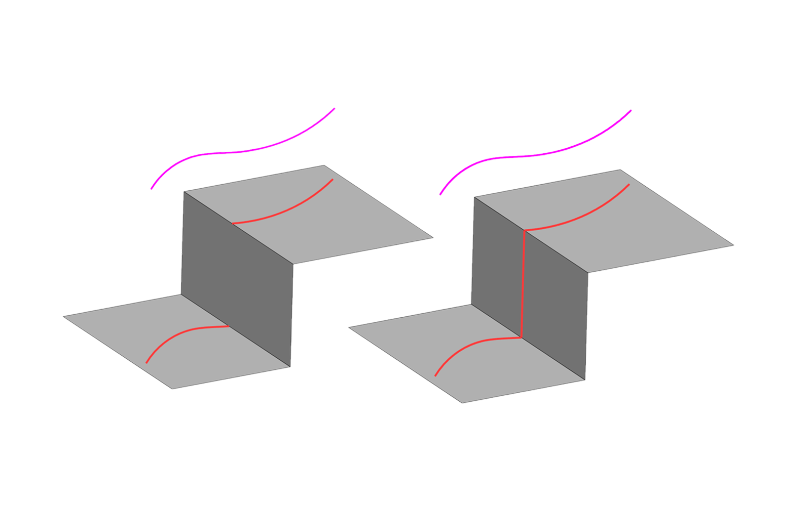
Fig. 2. Wireframe projection
An example of a new controlled-accuracy operation is shell trimming by a wireframe. Previously, if the curves did not align correctly, the operation could fail. Now, if the gap between the curves is within the user-specified accuracy, the operation proceeds with the expected result. Also, the operation now supports multi-component wireframes consisting of multiple unconnected fragments.
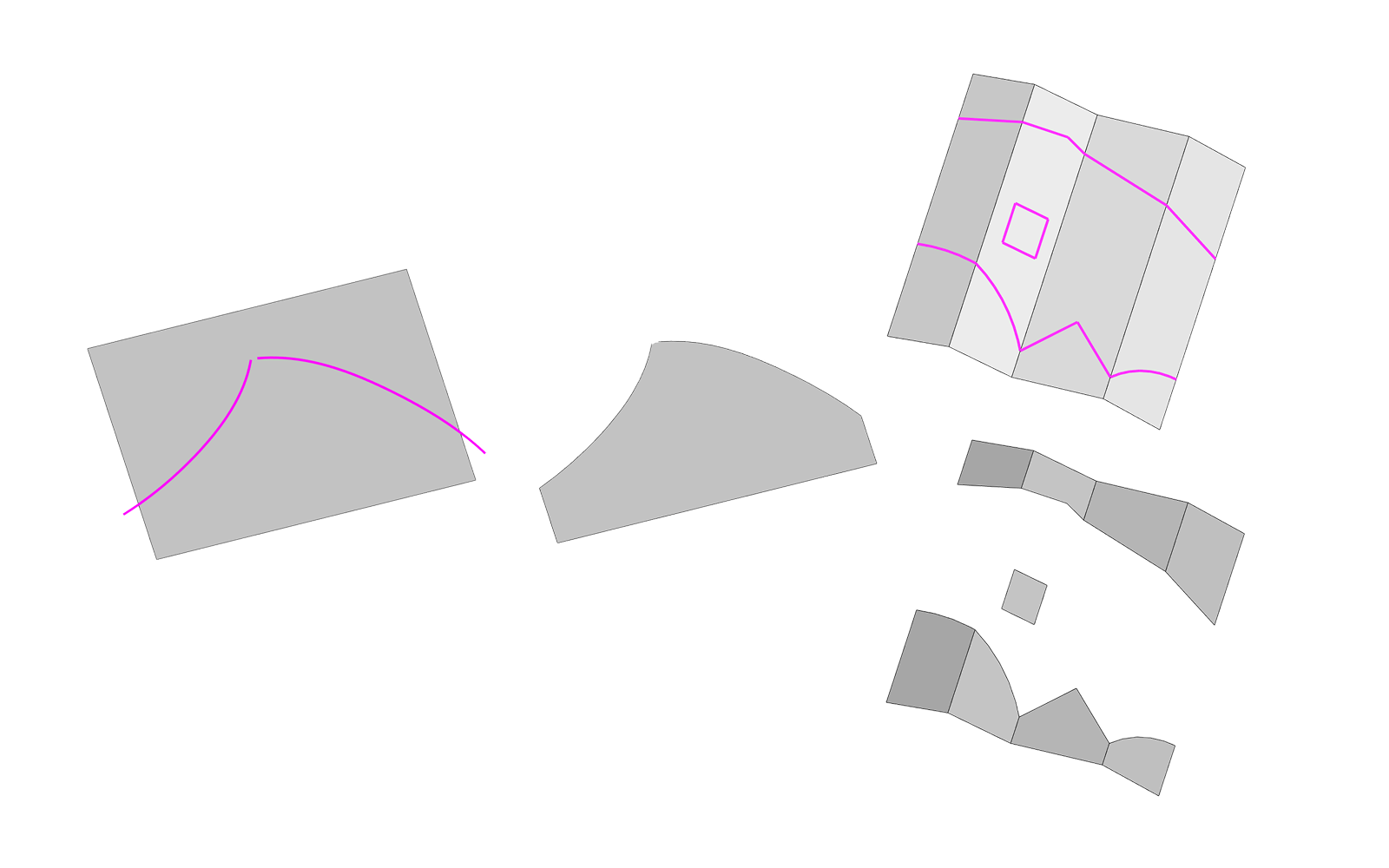
Fig. 3. Truncating a shell with a wireframe
Surface Modeling
Our surface modeling efforts focused on creating fillets of multiple, unconnected faces (Fig. 4). This operation is highly versatile:
- multiple fillet radius specification options.
- selectable cross-section shapes: circular arc or conic curve.
- different options for filleting groups of faces.
- the ball-rolling and disk-sweep methods for surface construction.
- several options for the side edges of the resulting fillet faces.
- The original faces can be preserved, trimmed to the fillet, or trimmed and stitched to the fillet.
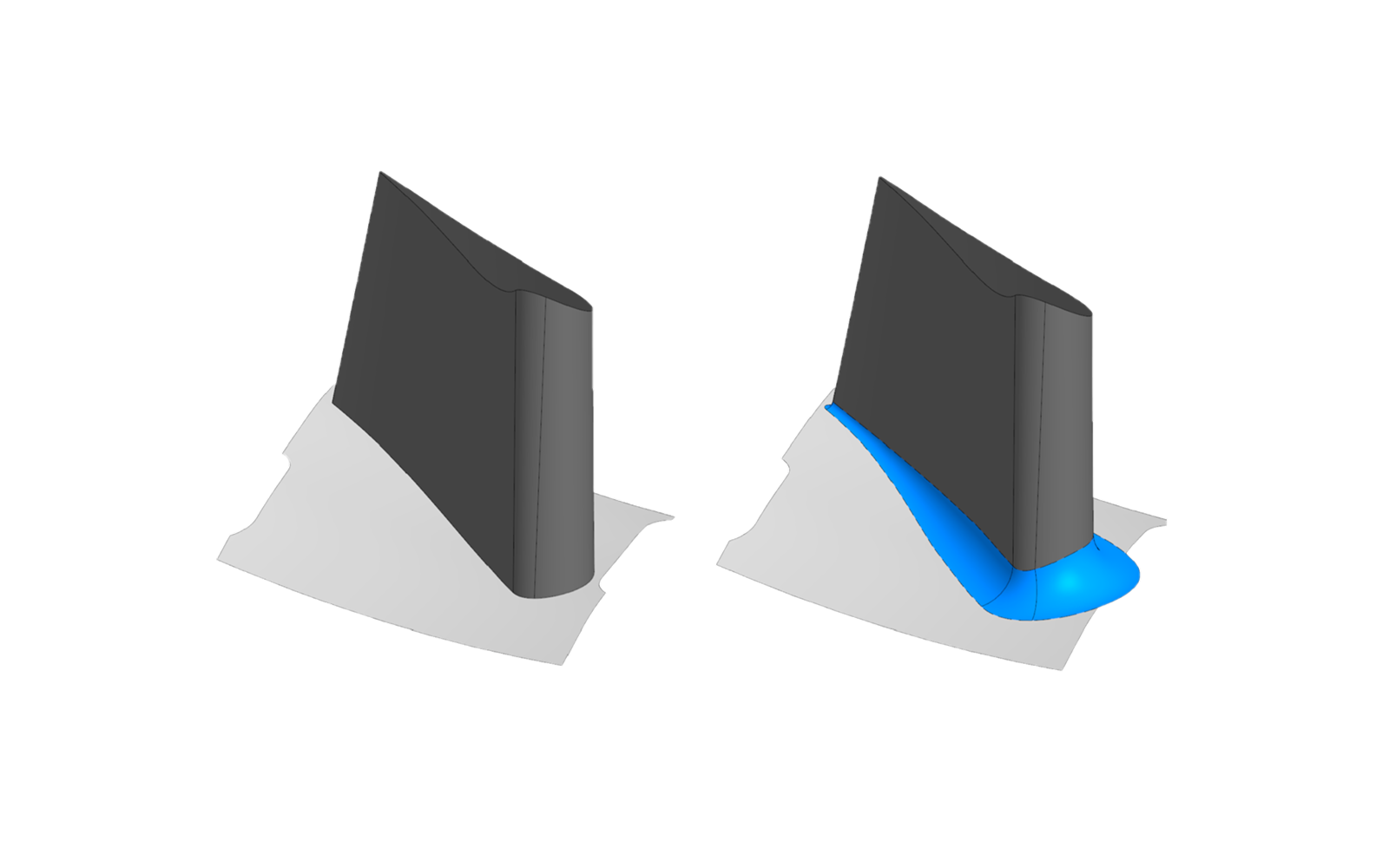
Fig. 4. Filleting faces
With all these features, you get a powerful yet flexible surface modeling tool comparable to those offered by leading global vendors.
Another improvement is the addition of new methods for specifying the radius of the fillet surface. The first option is constructing a fillet from the boundary curves (Fig. 5) located on the selected faces. This is available for both the ball-rolling and disk-sweep methods.
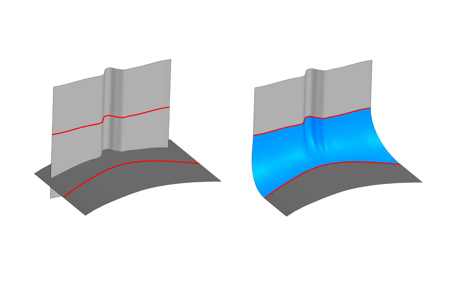
Fig. 5. Radius definition: from boundary curves
The second option is constructing a fillet tangent to a third group of faces (Fig. 6). In this case, the faces of the third group are not required to be mutually tangent. This option is also supported for both surface construction methods.
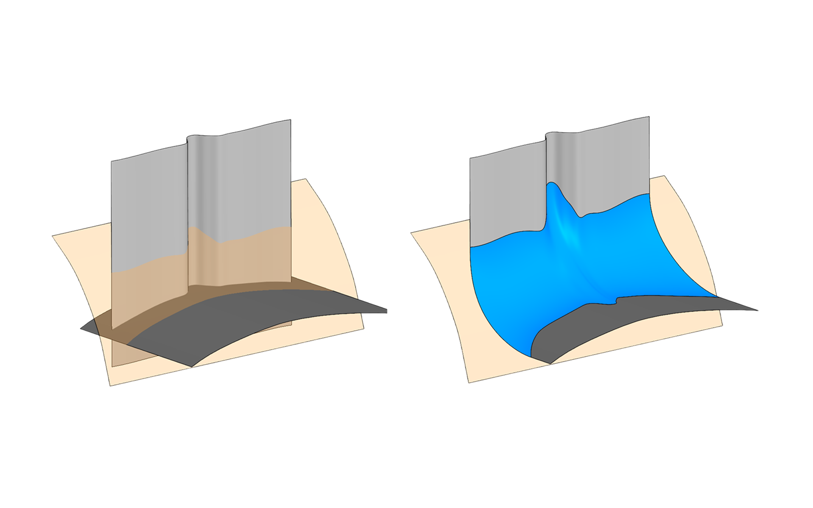
Fig. 6. Radius definition: tangency to the third face
In the third option, the user specifies a generalized function representing the radius change along the guide curve (Fig. 7). A 1D scalar function (e.g., linear or cubic) can be used.
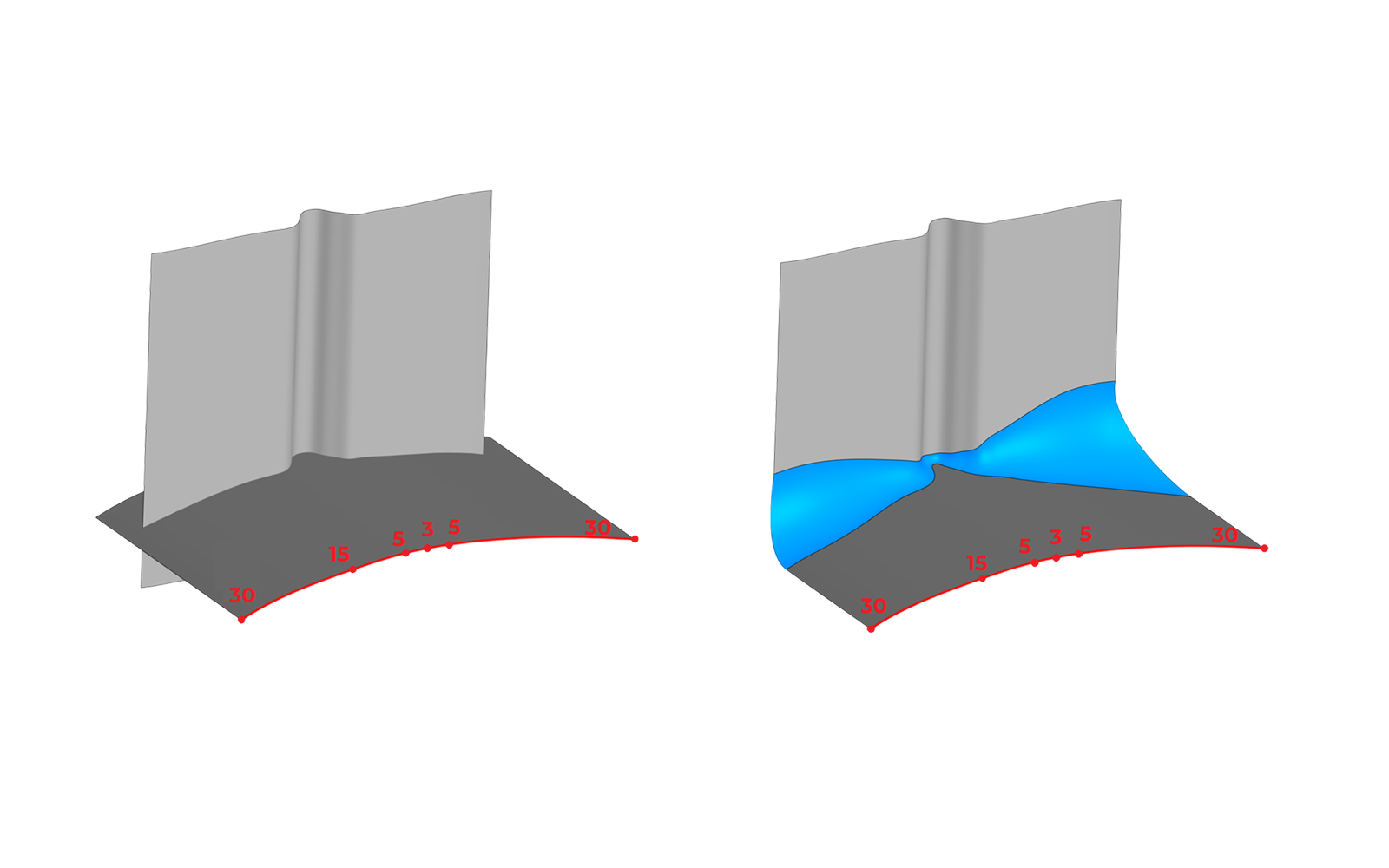
Fig. 7. Radius definition: functional law
We have also added a special function to specify fillet radius values at specific points along the guide curve. Besides the radius, the user can control the tangents of the radius function at these points for more flexible control over the shape of the resulting fillet surface.
We are working on a new fillet option to support a number of challenging cases. Usually, a drastic change in the curvature of the faces being filleted results in a self-intersecting fillet surface. We are introducing a special procedure to handle such cases. It works as follows: first, the problematic area is detected; then, this area is removed from the resulting fillet face and replaced with a patch. It guarantees, at a minimum, a smooth blend with the faces being filleted.
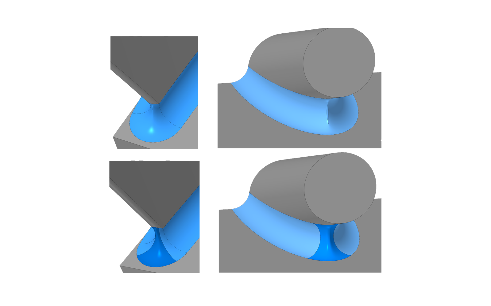
Fig. 8. Special fillet options
Solid Modeling
We have enhanced many solid modeling tools. The key updates address tolerant geometry in Boolean, extrusion, rotation, and sweep operations. We are adding controlled accuracy to more kernel operations. This is a major undertaking, but we are making good progress on several fronts.
A real highlight is using a generatrix defined by multiple wireframes in sweeping operations. In sheet metal modeling, we have enhanced the flat pattern operation for sheets with complex and filleted edges. We have also added new capabilities to the Taper operation.
We have made significant progress in constructing constant- and variable-radius edge fillets (Fig. 9). The kernel development team has resolved numerous issues affecting the smoothness of transitions between the resulting fillets and the faces being filleted, as well as between adjacent fillet faces.
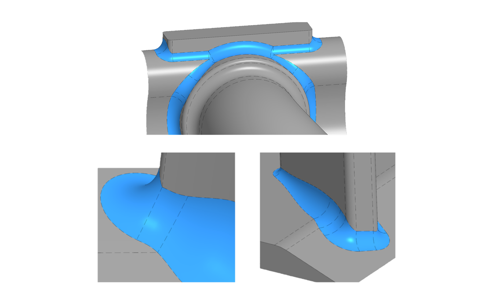
Fig. 9. Edge filleting
One of the key improvements is merging adjacent fillet faces. We focused on eliminating redundant fillet edges that occurred in some cases and raised user complaints. We are still working on a better variable radius fillet procedure. Key improvements: more flexible fillet radius definition and control, and better stability. Overall, we have recently made significant improvements to fillet functionality. We categorized all identified issues and grouped them into major clusters. This allows us to address entire classes of issues rather than fixing them individually.
System-Level Improvements and Optimization
The kernel’s system-level improvements focus on reducing model size both on disk and in RAM. As part of these efforts, we have improved the copy registrator of the kernel objects. Now it can track the lifetime of objects. The copy registrator is used in many kernel operations, such as adding thickness and filleting, to minimize duplication of shared data.
Other optimization efforts include eliminating unnecessary copies of surfaces when constructing intersection curves. We have also optimized the representations of NURBS curves and surfaces. As a result, file sizes were reduced by up to 40% for a number of models, which is a significant improvement. This work is ongoing and will continue throughout the year.
Attribute merging when combining and stitching faces has also been enhanced. Renaming of the MbMesh object primitive deserves special mention. Please refer to this C3D Labs blog post.
The extended C3D format now supports attribute-controlled partial model loading.
Another important area is logging of kernel operations. Its main purpose is saving operation parameters before the operation is executed. Initially, it was an in-house debugging project: we needed to save the operation parameters for subsequent playback. As work progressed, we realized that this feature would benefit our users, too. A user can save the inputs for a failed operation and forward them to tech support. The support team will reproduce the situation for faster error fixes.
To use this feature, create a special system variable and initialize it with some value. When the library is loaded, this variable is read, after which the library begins logging. The logs are saved as JSON files and C3D files containing the geometric objects involved. All generated files are placed in a specified folder.
C3D Kernel: Plans for the Future
We will continue developing controlled precision in the kernel operations. Another focus is filleting, particularly variable-radius fillets. We will enhance the new option to eliminate self-intersections in fillets, and fix the remaining face filleting issues.
We will optimize data sharing in kernel operations to reduce model sizes in RAM and on disk.
Another important area is cross-platform kernel unification. We are also enhancing the basic kernel operations. In particular, it is the extension of NURBS surfaces with various options.
In sheet metal modeling, we plan to add support for press-brake bending. In response to user requests, we are going to provide access to intermediate models created during sheet metal operations.
To accomplish these tasks, the kernel development team has expanded significantly. Over the past three years, its size has more than doubled. Growing faster would have slowed development because of the additional time needed to onboard new employees.
The geometric kernel development team is now capable of tackling the most complex challenges. There are no fundamental obstacles ahead: we have already demonstrated this by delivering complex projects under tight deadlines. The team’s expertise and experience will support the kernel’s further development.

Andrey Tumanin
Head of the C3D Modeler Development, Ph.D.
C3D Labs