Alexander Spivakov, leader of the C3D Converter team, C3D Labs, talks about the purpose of the converter in the C3D Toolkit, C3D Converter use cases (migration and multiCAD scenarios) in your applications, introduces the new improvements, and shares the plans for the future development of the converter.
What is C3D Converter, part of the C3D Toolkit and what does it do? Globally, it solves two problems.
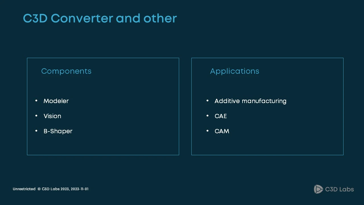
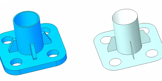
Fig. 1
First, the module provides all the other C3D Toolkit components (C3D Modeler, C3D Vision, and C3D B-Shaper) with initial data. It means importing from files. The second problem is opposite to the first one. Once we have created a 3D model with the other components, it may be necessary to transfer the model to another application or a higher-level system beyond our components. This also applies to simulation, printing, etc.
What do we use for that?
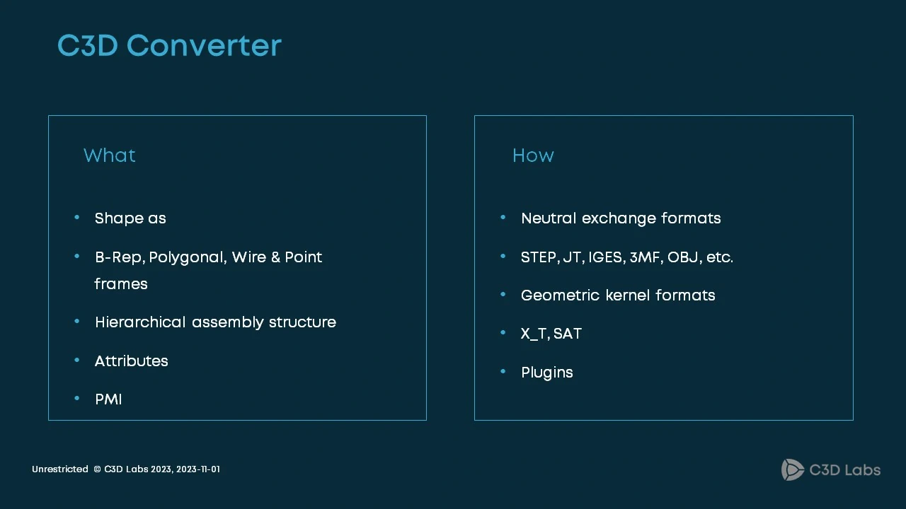
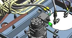
Fig. 2
There are two key approaches. The traditional approach is to read and write files of different formats. These are both proprietary kernels (mainly grands) and open formats. The second category is larger. It includes ISO STEP, JT, and other commonly used formats: 3MF, IGES, OBJ, STL, etc. The second approach is more custom: using plugins to read formats that are not available out of the box. We mostly deal with the shape of bodies. We convert such shapes as B-Reps, polygonal objects, points, and curves. The converter also handles assembly structures, attributes, and PMIs.
Let us focus on two specific use cases where C3D Converter is fully utilized.
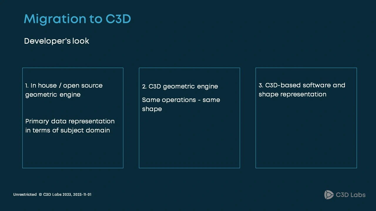
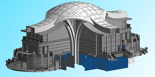
Fig. 3
The first is migration to an end-user application. Consider migration from a third-party vendor like SolidWorks or AutoCAD, for example, to KOMPAS 3D or nanoCAD. What does it look like? Suppose a company has an IT ecosystem based on the products from a Western vendor. The pillar of the ecosystem is CAD, solution also from an international vendor. Over time, it becomes clear that domestic solutions are more appropriate for a variety of reasons. What should be done? Install the domestic software and convert all the existing documents and models. It is a complete data migration. This scenario also occurs when we receive enhancement or bug fix requests. It is quite a challenge, but we do face it sometimes.
Take a look and a corporate IT ecosystem.
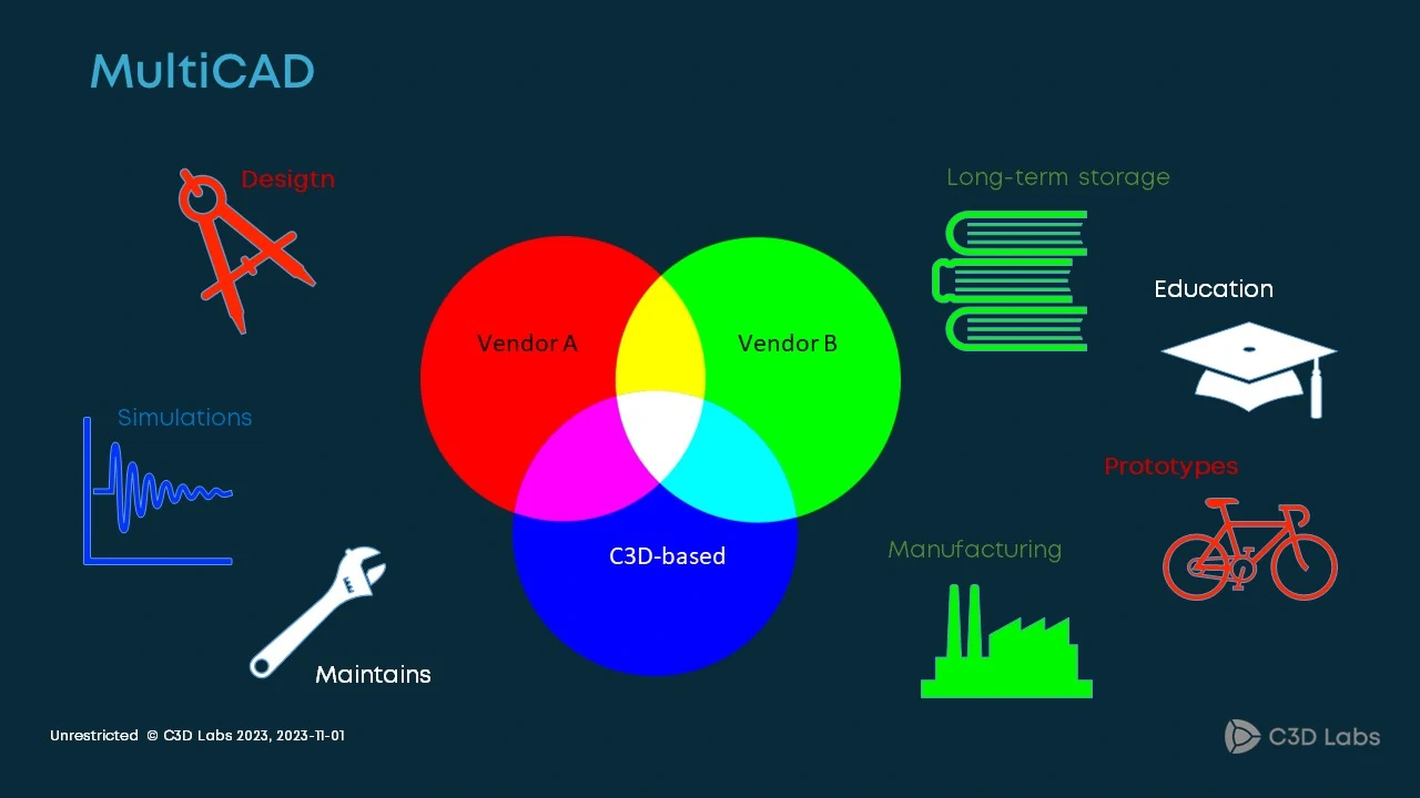
Fig. 4
The real ecosystem is embedded in a variety of business processes: R&D, employee training, prototyping, manufacturing, etc. The input data in this case are the files created by a solution from a western vendor (e.g. Siemens). There may be some other component B. The goal is to integrate C3D-based products into the ecosystem as a replacement for international solutions.
Why is a simple replacement not enough?
There are several reasons why you can't migrate. First, the migration timeline may be too long. In other words, it may require a large amount of rework that will take time. There may be a need to fine-tune the end-user applications as well. Such changes should be implemented and tested. It also takes time. Second, the customer's business runs with all its complicated processes, so it is impossible to just use the existing tools without the ability to roll back to the previous system. Third, the migration may be hindered by some industry-specific circumstances. We call all this a multiCAD system.
To be more specific, let us talk about the NX ecosystem.

Fig. 5
Suppose, we need to replace the CAD solution, let's say, NX with KOMPAS 3D. We also need to support the CAD format used by the PLM system. The problem looks like this: read and write JT, and read the .PRT format. What kind of data should we convert? All of them: B Rep, mesh, and PMI.
The C3D Labs solutions have been supporting JT since 2018. It seems nothing new has come since then.
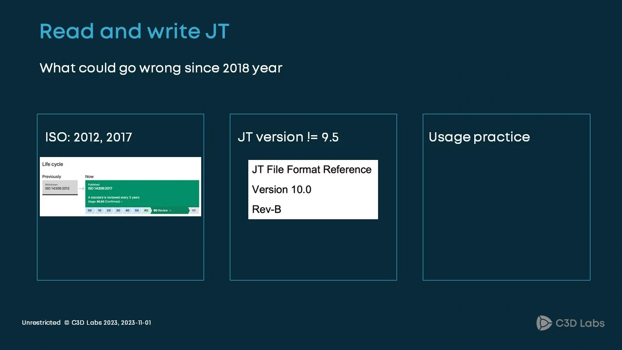
Fig. 6
Wrong! The innovations are plentiful. First is the support for the ISO format, which is revised every five years. Initially, we supported the 2012 version. The current version ISO 2017 will soon be replaced by ISO 2022 and ISO 2023. Second, there is another flavor of the JT format that is maintained by Siemens. The company releases updates, but it does not announce or document them. Still, we should be able to read this format. Third, actual use cases are more important than just formats and documentation. Sometimes, everything seems to comply with the standards and other documents, but it still does not work.
Let us take a closer look at the JT format.
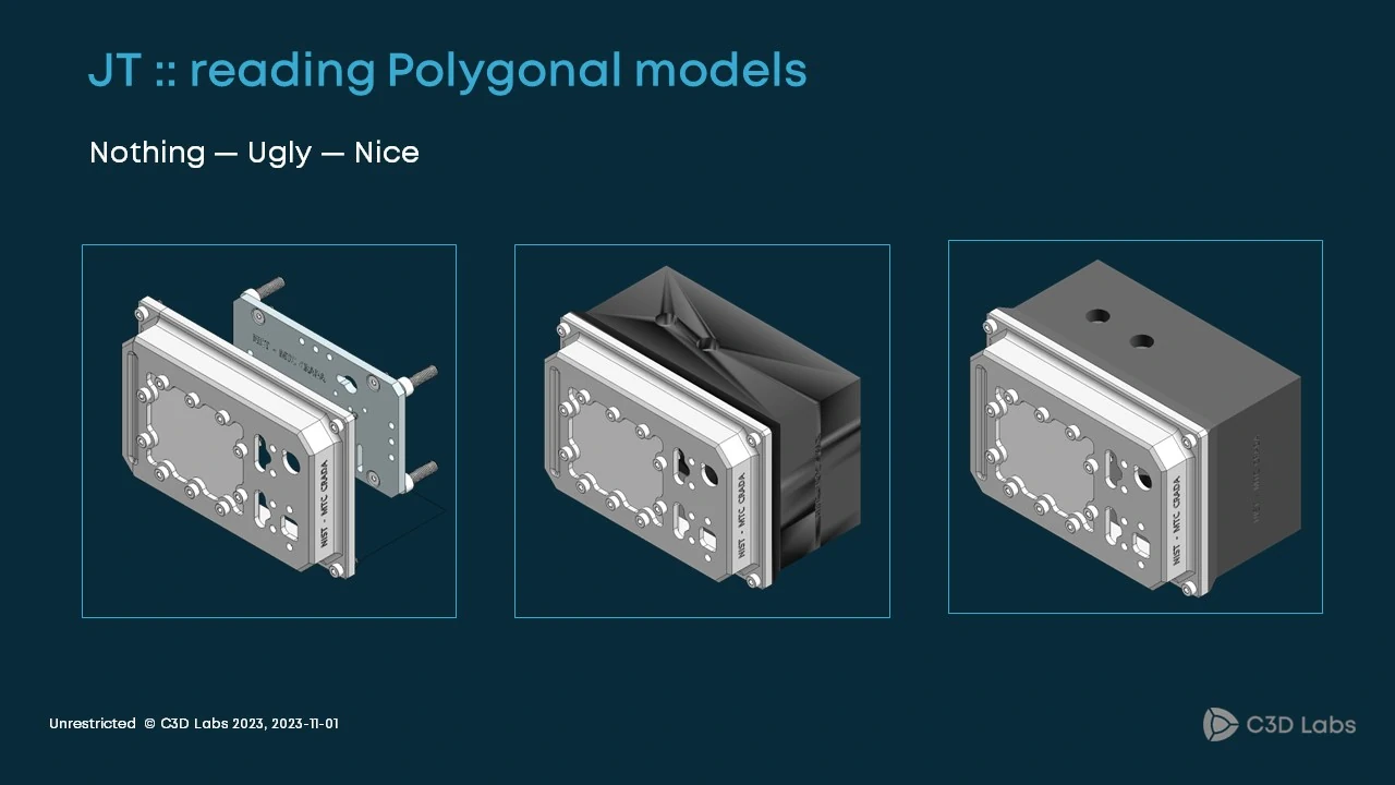
Fig. 7
This format simultaneously supports B-Rep and polygonal geometry, the latter of which is mandatory in our use case. The slide shows the evolution of handling mixed models that include both mesh and B-Rep geometry. At first, we failed to import anything: we got the polygonal geometry error. Later, the situation improved somewhat. We managed to read the format but faced some visualization issues. Eventually, we achieved optimal import and visualization capabilities. This is bug fixing.
The boundary representation (B-Rep) deserves special attention.
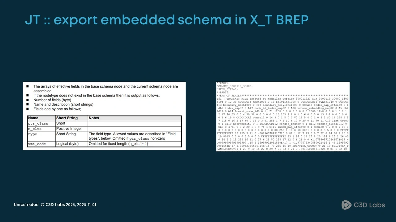
Fig. 8
The JT format uses the Parasolid X_T representation, as far as we can tell. Providing support for current Parasolid X_T versions is our annual business. Exporting was more challenging. Concerned customers reported that they could not open the exported JT files. At the same time, when we exported the same models to X_T, there were no problems. We managed to find the culprit. The point is that the X_T format supports embedded schemas. The schemas are used as a compatibility tool. What seemed uncritical eventually became a problem. Through close observation and experimentation, we were able to export parts to NX.
After the problem with the parts was solved, we faced the assembly challenge.
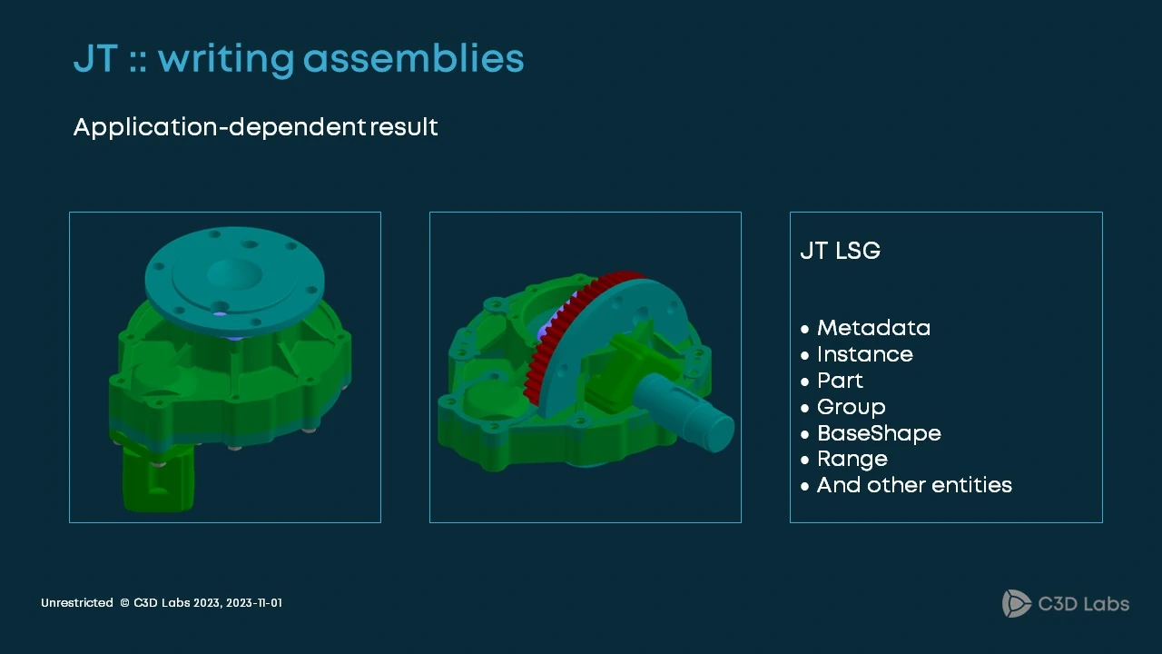
Fig. 9
When we exported the gearbox assembly from KOMPAS 3D, the origin shifted (this is a real case). The LSG (Logical scene graph) segment represents the assembly structure in the JT format. It contains many types of entities (Metadata, Instance, Part, Group, etc.). Which one to use is unclear. The same model could show drastically different behaviors. In the JT2Go viewer, all the parts in the assembly were in their correct locations. But when we opened the same file in the CAD system, we got the origin shift. We were able to meet these requirements and make the converter NX-compatible without compromising performance.
Reading the native .PRT format is one of the most challenging issues.
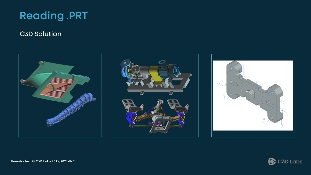
Fig. 10
We faced it in 2019, and at the time, we had a choice: build an in-house solution or license a third-party component. Our customer, the KOMPAS 3D development team, decided to purchase Capvidia which supports not only .PRT but many other proprietary CAD formats. We just had to implement an integration module. The module had to meet the Capvidia requirements and be compatible with our 3D kernel. Within a year we learned to read not only the .PRT format, but about a dozen other formats (scanned meshes, assemblies, etc.). But it turns out that what is easy to get is even easier to lose. So, we had the plugin interface module. What to do next? We found another technology partner: CAD Exchanger. Its team quickly reproduced the full functionality of what had been available before. There were no more import issues. Nevertheless, the experience was painful, and we began to develop an in-house solution. Now we get same 3D-models for further design and rendering from our own solution.
Now about something more exciting.
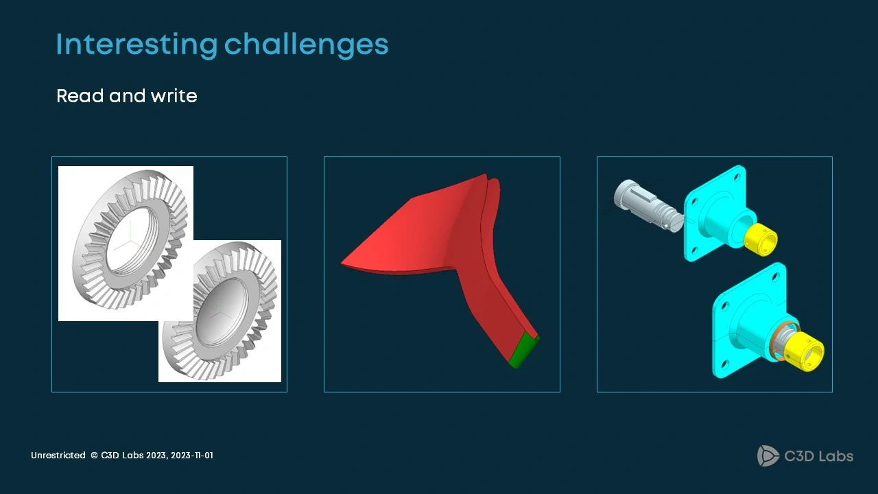
Fig. 11
Bug fixing is an ongoing activity. What did we do? When handling the Parasolid format, we needed to construct two-edge fillets. We closely studied the JT format, particularly with the length units, and geometry.
We also provided out-of-the-box support for the new 3MF format.
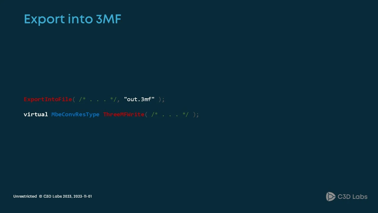
Fig. 12
This format is used for 3D printing with much stricter mesh requirements and the result should be suitable for 3D printers.
Finally, let us talk about the C3D Converter roadmap.
Fig. 13
As for out-of-the-box capabilities, our goal is to read the 3MF format, support the SAB format in addition to SAT, and continue to improve conversion quality. In terms of plugins, we already support .PRT files. SolidWorks, Creo, and IFC are coming. For SolidWorks, we have already done a lot of work. We can handle many parts and assemblies, and support PMIs.

Alexander Spivakov
C3D Converter Team Leader
C3D Labs