The next release of the C3D Modeler geometric modeling kernel will add construction of conic section surfaces.
A conic section surface can be obtained by moving a flat generatrix along a spine curve. (A generatrix generates curves by moving entities along paths.) As it moves, the generatrix can change its shape according to a controlling function. The plane of the generatrix maintains orthogonality to the spine at their point of intersection. Quite often, the generatrix is a part of a plane algebraic curve of degree 2 that begins on one guide curve and ends at another guide curve.
Figure 1 shows an example of a conic section surface generatrix. The generatrix starts at point A, and then ends at point B, where the plane of the generatrix intersects the two guide curves.
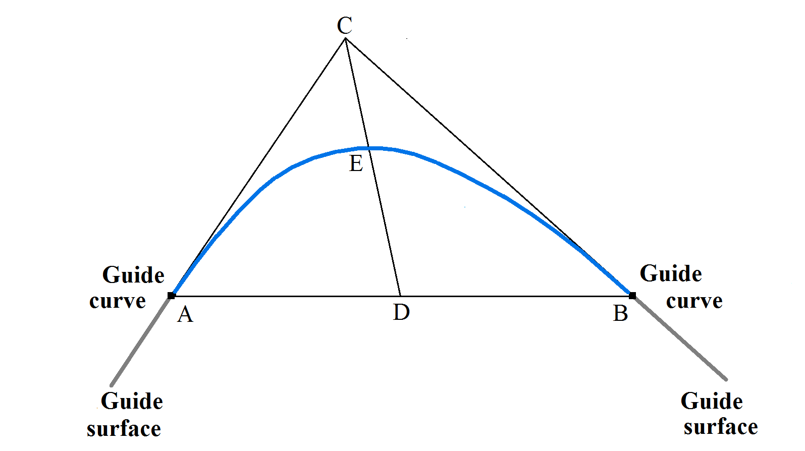
Figure 1
The shape of the generatrix is controlled via the discriminant of the conic section. The discriminant of a conic section is equal to the ratio of the lengths of segments DE and DC (see Figure 1). Point C is the intersection point of the two lines, tangent to the generatrix in its end points. Point D is the midpoint of the segment AB. Point E is the point where segment CD intersects with the generatrix.
To construct a conic section surface, you need the following as input:
- A spine curve
- Two guide curves
- The function that changes the discriminant
- The directions of the generatrix at its ends
The directions of the ends of the generatrix can be set using two surfaces or another curve, which is the intersection of lines tangent to the ends of the generatrix.
The function for changing the discriminant of a conic section can be specified by several ways. It can be set explicitly; calculated from an additional curve that the surface must pass through; or else calculated from an additional surface that the conic section surface must touch.
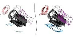
The conic section surface can be made to smoothly join two specified surfaces. To do this, the guide curves must lie on the specified surfaces. Figure 2 shows a conic section surface that smoothly connects two surfaces. The discriminant of the generating curve of this surface is 0.5.
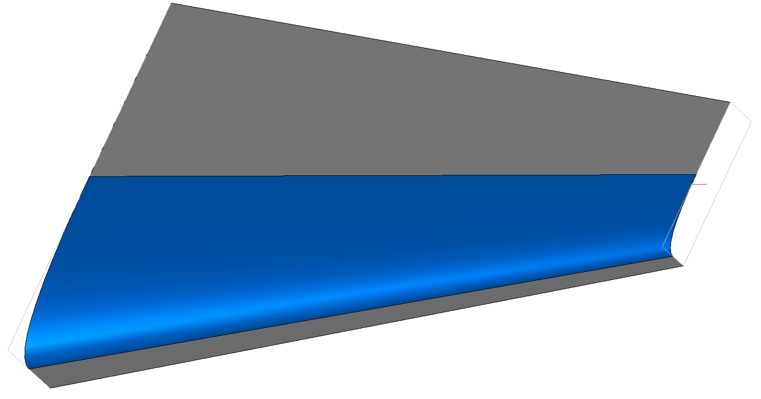
Figure 2
In general, the discriminant of the conic section surface can change according to a given function along the spine curve, and the guide curves can be composite. The generatrix can be any flat spline curve for which you can construct some triangle ABC (see Figure 1). The curve must be located inside the triangle ABC and touch the sides AC and BC at its ends. When this is the case, the discriminant function may be omitted.
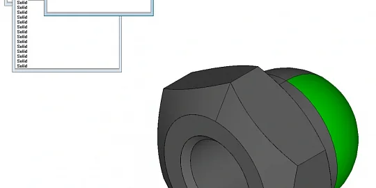
Conic section surfaces can have many different forms. Figure 3 shows the surface formed by the movement of a circle along a straight spine.
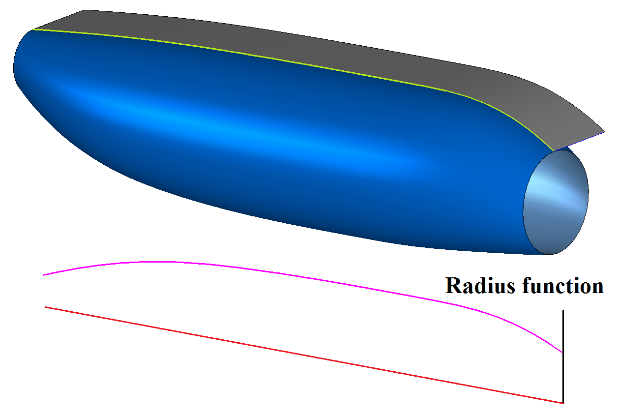
Figure 3
In Figure 3, the radius (magenta curve) of the circle changes along the spine (red) according to a given function, and the conic section surface (blue) touches the specified guide surface (gray) at the points of the specified guide curve (green).

Author:
Dr. Nikolay Golovanov
Head of Development at C3D Labs.